This afternoon I completed the “color” preamp and tried it out. I am very happy with the results.
This project started on Feb 3rd when I marked the BUD AC-403 aluminum chassis box for drilling. I had done a layout in the morning with which I was satisfied and decided to move forward. It looked like this on the 3rd.
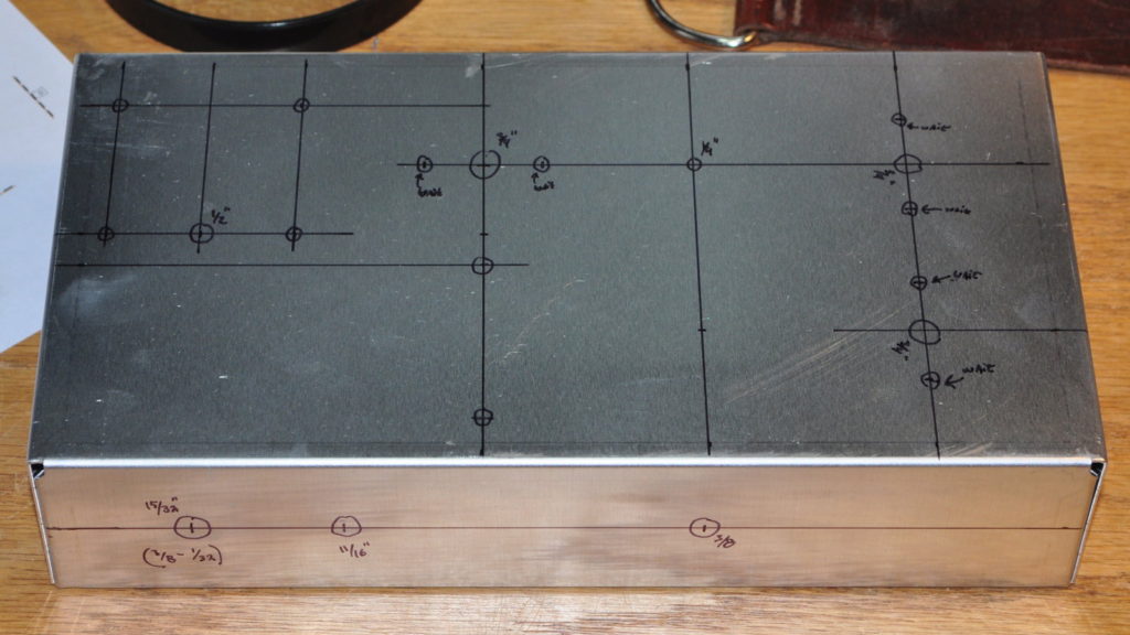
I had decided that I needed a “quick” project to work on while waiting for better weather to work on the 6AS7 SET wood chassis. We are currently having mixed rain, snow, and sleet, so I don’t think the better weather has as yet arrived. But the color preamp got its final testing this afternoon. Here it is on the workbench today.
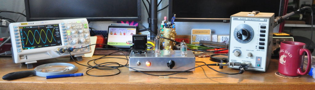
I had made a simple modification yesterday to account for the unintended buffer behavior and run some performance numbers on both channels. These are the numerical results.
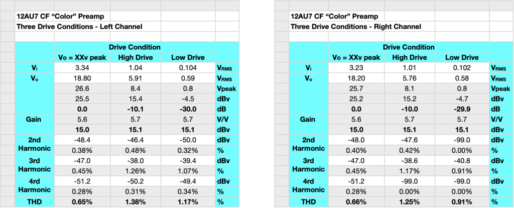
The amp has a peak gain of 15dB. In the picture above you’ll see the pointer on the volume knob at top dead center. I set the knob so that this is the unity gain position. Clockwise rotation increases gain up to about +15dB. Counter clockwise rotation decreases gain to about -26dB. The extent of the rotations are not symmetric but that’s ok. A quick visual check can always assure that the gain is either positive, negative, or nominally zero dB.
After the technical testing I gave the preamp an audition with a little class D solid state amp which I use in my office as a computer sound monitor. This is the class D amp I discussed in October 2020 in my "That “Other” Project" post. The amp is just driving a couple of small monitor speakers. But even with these the change was very noticeable. Here’s the setup.
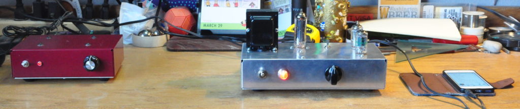
The class-D amp is on the left, the preamp is on the right driven by my iPod. I wasn’t sure that I’d be able to notice the difference with the small speakers, but the preamp really warmed up the sound. I was presently surprised.
This project, although it’s taken less than three weeks, has been a series of complications, one after another. First there were the issues with drilling the chassis. They there were access issues trying to work in the small enclosure. This was followed by parts availability issues. And finally, there was the unexplained buffer behavior I needed to explain. It’s this final issue I would like to discuss in more detail.
This input for this preamp is tied directly to the gain stage without a volume control. In order to prevent even the hottest line signal from overdriving the gain stage, I set the grid bias at ≈-6v. So the gain (or “color”) stage should never be overdriven. However, in initial testing, the preamp output was bottoming out with a peak input of only 2.2v. So I checked the gain stage without the buffer and found that it was operating cleanly with a gain of 11.4 and a grid voltage of ≈5.5v. This gave an output voltage of about 63V peak. So it was the buffer which was bottoming out at about 25 volts peak input.
The buffer I used for this project was an existing design I have used before and verified that it can handle an input voltage of almost 80v peak. Clearly something was amiss. So I embarked on a day long investigation rereading notes and textbooks and doing lots of circuit calculations. Finally, I discovered the culprit. There in my notebook was this note.
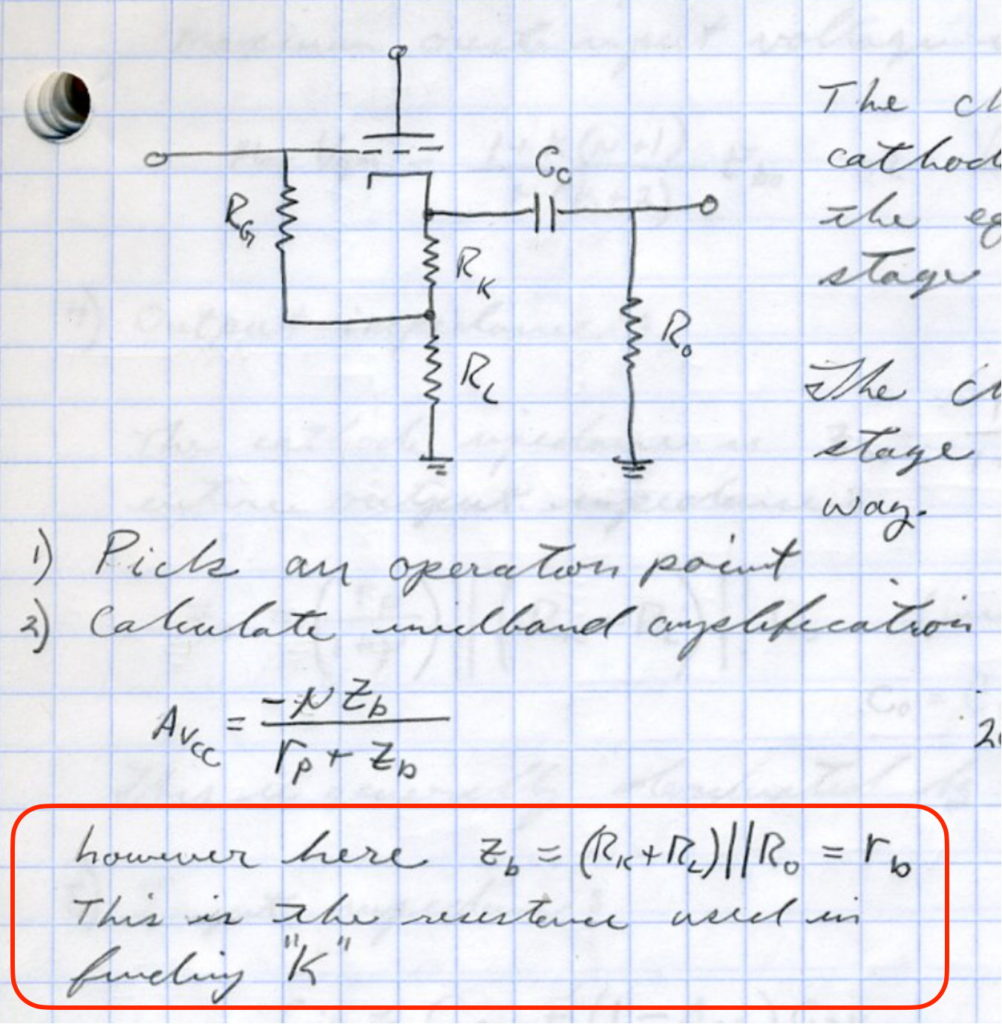
What I had forgotten was the conditions under which the buffer would be operating. The cathode follower was designed as a driver for RF pentodes operating at 100MHz. The input impedance of the pentodes was set by grid resistor at about 250kΩ. This is the “Ro” in the diagram and circuit above. But in the color preamp, the value of “Ro” was just a 10kΩ potentiometer. The result was that the maximum voltage swing that the buffer could handle was greatly reduced.
I had failed to account for the change that reducing the final load from 250kΩ to 10kΩ would have on the buffer. It was a simple mistake but I really should have caught this before I started. However, once the circuit was in my notebook, I was doomed.
Had I set out to design the buffer from scratch for this preamp, I could have addressed this issue. However, as the circuit was completely assembled prior to me finding the issue, I was reluctant to tear into the circuitry to fix it with en entirely new buffer design. So I installed a work around.
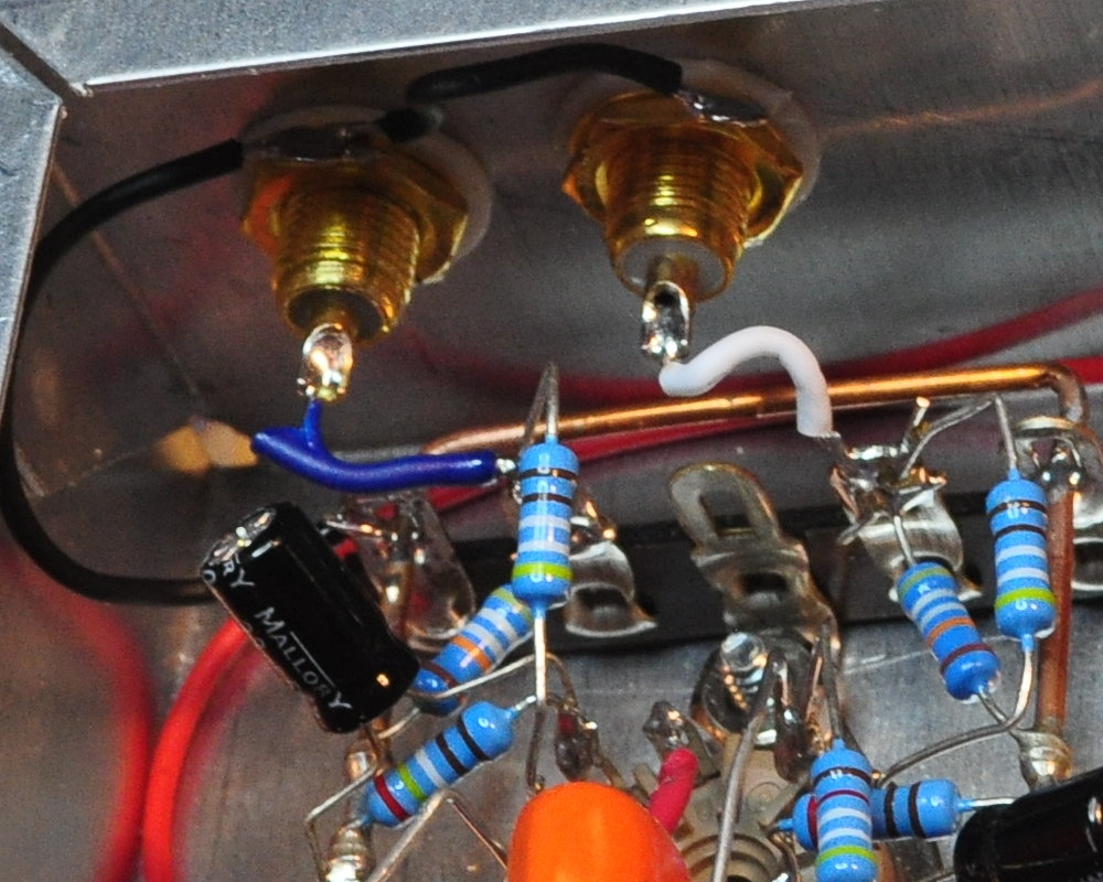
Because the grid circuit of the gain stage had 500kΩ grid resistors, I just removed the wires which tied the RCA jack to the stage and replaced them with 500kΩ resistors. This forms a -6dB pad on each input doubling the input voltage before overload occurs. You can see this substitution in the following to pictures.
The first shows the original input wires.
And the second shows the wires replaced by 500kΩ (or really 499kΩ) resistors.
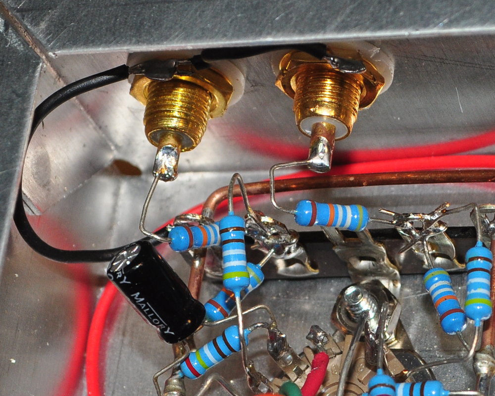
The result is that the preamp can now take a maximum input voltage of about 4.5v peak without overloading. This should allow it to be used with virtually any line level source. This is not my preferred approach. And I am working on a better buffer design which will allow the gain stage to perform as intended without the front end pad. But that rebuild will definitely go into a bigger chassis.
As always, questions and comments are welcome.
Update 21 February 2022: I forgot to post the power supply schematic I used for this project. Here is the schematic as drawn in my notebook.
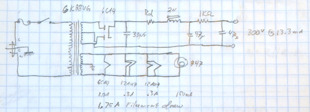
The value of Rd I used was 4kΩ / 1.5W resulting in a B+ of 286v. The 6K88VG is wound for a mains voltage of 115v and my mains run about 122v or about 6% above the assumed primary voltage. With a 3kΩ I could have come very close to 300v but I didn’t have one on hand that could handle the power. If using this schematic, adjust Rd as appropriate for your location.