With all the distractions this week, I’m not quite as far along as I would have hoped. But all the top plate wiring is done, the power supply sections are complete, and the 6AS7 power stage is complete.
Here’s how the top plate looks from the bottom. It’s finally starting to look like an amplifier.
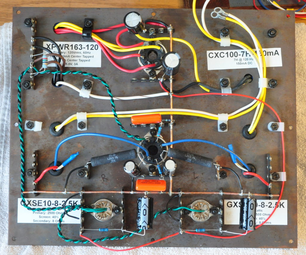
At the top of this picture you can see the 33µf primary filter capacitor and the 100µf cap that comes after the 7H primary filter choke. At the bottom you can see the 1kΩ/33µf power supply filters for the left and right drivers.
In the center of the picture is the wiring for the power stage. I used oversized power resistors, 10W rated dissipation verses the 5.3W actual dissipation because they had a much larger surface area to spread out the heat. The coupling capacitors are CDE 716 Series 0.1µf capacitors. This value puts the -3dB low frequency for this coupling at about 2.8Hz for a 20Hz loss of only about 0.6dB. With the natural low end response of the drivers and the reasonable transformer performance, this amp should have a nice well controlled low frequency response.
Next comes wiring the driver sections. Once that’s done I’ll install the top plate on the chassis and make all the appropriate connections. Then it will be time for testing.
As always, questions and comments are more than welcome.