Here’s the salient point about putting your entire amplifier design and build process on the internet for all to see. Invariably, regardless of how well everything is going, things always arise which manage to keep you humble. And today it happened again.
Today I got the 6L6 SE-UL on the test cradle and did the initial power up and voltage checks. Here is the amplifier and cradle sitting on my desk.
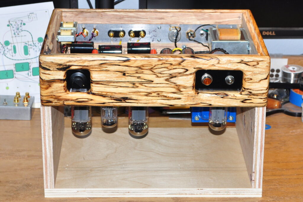
In the amplifier are a brand new pair of matched JJ 6L6GCs, a JJ GZ-34 rectifier, and an old stock GE 6SL7 I tested back in March and talked about in this post: Overlapping Projects and Getting Things Done. However there is one thing that is not in the amplifier; a voltage dropping resistor. Here is the wiring where the dropping resistor should be.
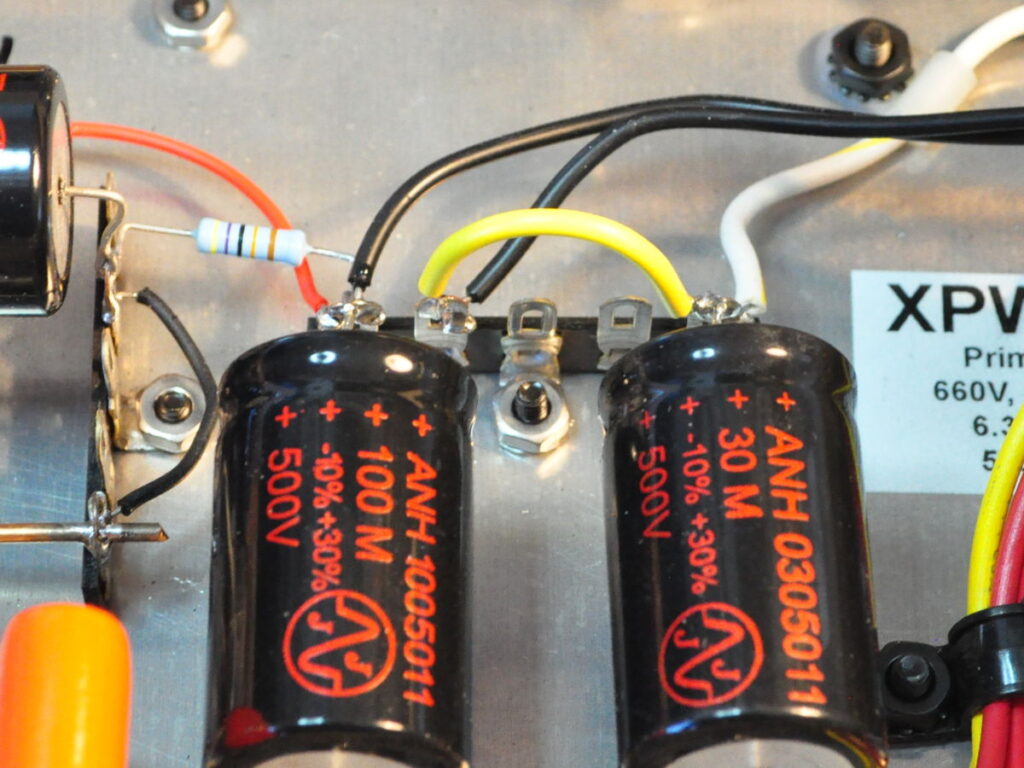
It’s just a piece of wire where I thought I’d be installing a resistor to set the B+ voltage. The 470kΩ resistor on the left is the power supply bleeder resistor.
When I first designed this amplifier the power supply was a little bit different. Specifically I had assumed an Edcor CXC-7H-150mA primary filter choke. The Edcor choke has a nominal series resistance of 104Ω. And this is the value I used in my design calculations.
However, I subsequently decided that I wanted to be able to swap in KT88s and I decided that the filter inductor needed to be upgraded to a 200mA model. I was also laying out the top plate at that point and convinced myself that I wanted to clean things up by putting the primary filer inductor under the top plate. So naturally I chose my favorite open frame filter choke, a Triad C-14X 6H 200mA choke. There’s only one catch, the Triad has a nominal series resistance of 150Ω. That extra 46Ω of resistance accounts for about 19V of additional drop in the B+. As a result, without a dropping resistor, the power stage B+ is at 385vdc. About 15v below my 400vdc target. I never accounted for this design revision.
Now this is only about 3.8% below target which should have virtually no impact on performance. But it does mean that a dropping resistor is not required. Hence the little loop of yellow wire in the photo above. I knew going into the design, after I changed power transformers from the XPWR011 800V model I had on my shelf to the 660V XPWR178, that the B+ was going to be close. But I had assumed a little high, not a little low. However, the bottom line is that this is close enough to not cause me any real concern. It’s just a little embarrassing that I didn’t catch it before actually powering up the amplifier.
When I get a little more time, I’ll record all the operational voltages, put the base plate on the chassis, and proceed to testing. This amplifier is almost complete.
As always, questions and comments are more than welcome.