Over the last several days I’ve made some progress on the layout of the new project. This is about the point where it’s time to start looking at wood.
The unit will have multiple inputs, an active “preamp” for adjusting gain levels, and meters for monitoring output levels. All of this needs to fit inside the unit. I decided that the tubes will be mounted horizontally on a vertical plate This makes the layout a little simpler. Here is my first attempt at the internal layout. I think I’m fairly happy with this so far.
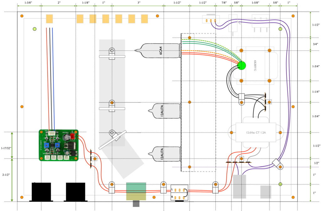
This layout doesn’t include all the wiring, but it does show where all the major components should reside. Power transformers and circuits are all on the right, the active electronics are mounted on the vertical plate directly behind volume control, and the signal wiring and meters are on the left. With appropriate lead dress, I believe that this can be made very quiet. I may also include tube shields in this build. Just to minimize any interaction between the tubes and the signal lines running right by them (that’s the gray region to the left of the tubes).
The active electronics should be fairly straight forward. It is a simple gain stage and buffer. The design is for a total of ≈20dB of end to end gain. This means that the gain control should behave exactly as it does on the 12AU7 Color Preamp. The control will decrease signal level when set left of center and increase signal level when set right of center. Here is the schematic for the active electronics.
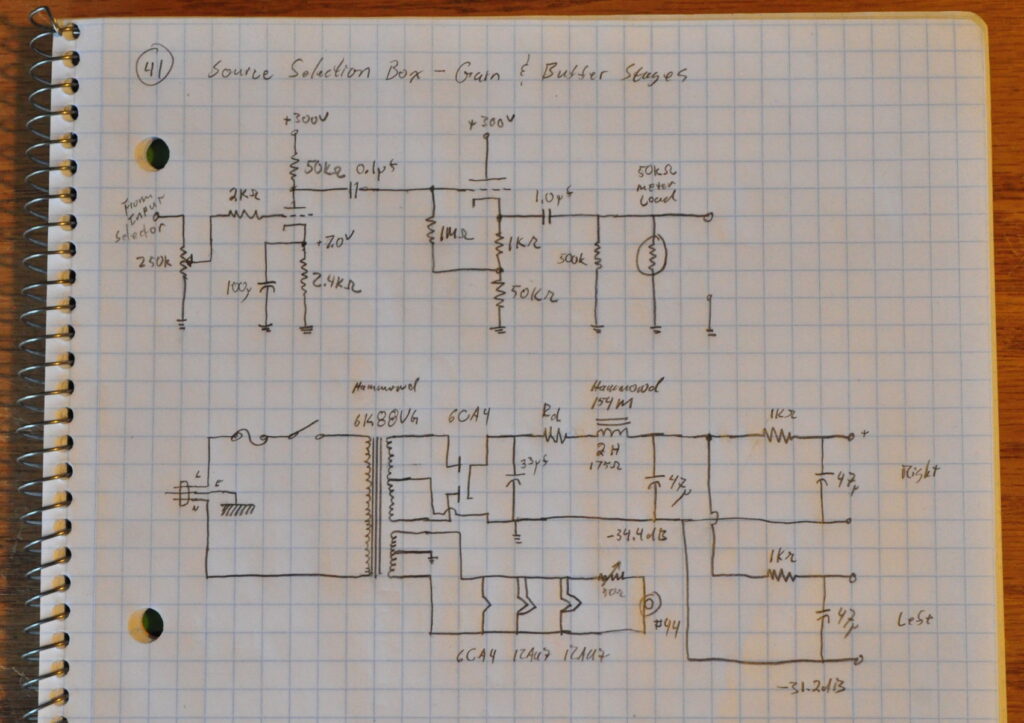
I have placed the volume control up front. This is for two reasons. First, this keeps the signal swing in the gain stages very small thus minimizing distortions. Second, it keeps the signal levels into the buffer stage small. This means that the drop in allowable buffer input voltage when the load impedance gets small doesn’t affect the performance (i.e. amps to which it’s connected may have input impedances as low as 10kΩ). I also split the power supplies so that there is lots of isolation between channels (≈62dB@120Hz + PSRR).
The vertical plate is eight inches long and three inches high. With the angle mounting bracket at the bottom this still leaves ample room for component placement. Here is the rough layout of the active electronics plate.
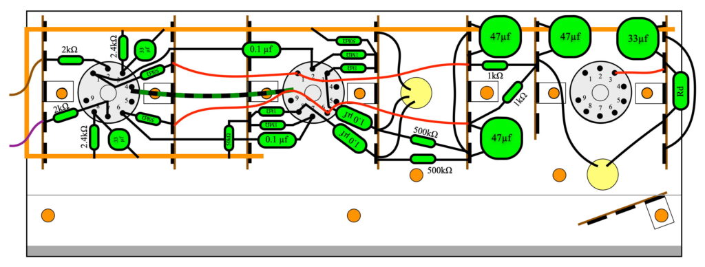
This view is from the right hand side showing the component side of the board. The input gain stages are on the left, the buffer stages are in the center, and the power supply is on the right. The 2H power choke is mounted on the tube side of the board near the bottom. Its leads come through the yellow hole below the rectifier socket.
The other yellow hole is a penetration for the output signal leads. However, now when thinking about it, I may route these line over the top or around the side. There is a risk of ground coupling if I leave it like this. I may need to think about this a little more.
This week I’ll probably select some wood for the chassis and get to work. I like to get the chassis glued up prior to cutting all the metal. This way, if the wood moves or does not come out exact, I can adjust when cutting the metal.
As always, questions and comments are welcome.