I have the initial set of data with the power supply prototype using the Edcor XPWR011 power transformer. It is enlightening and clearly shows which amplifier I need to build next.
I talked about waffling on the next amp project back in December. The reason was that I wasn’t sure that the 800VCT secondary of the XPWR011 was sufficient to produce the B+ needed for the triode strapped KT88 design I had in mind. This meant that I might instead finally build the triode strapped 807 amplifier for which I purchased this transformer almost ten years ago.
To help me make this decision, I decided to build a prototype supply which would allow me to test the transformer’s capabilities with a couple of different rectifier tubes. Here is the simple schematic of that prototype.
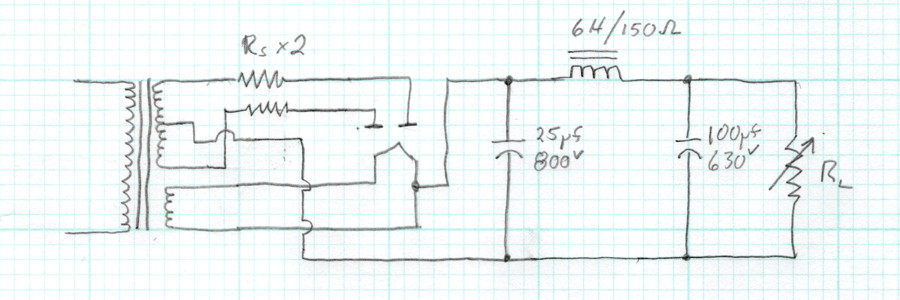
This is just a simple supply with a reservoir capacitor and a single stage of LC filtering. This is sufficient to characterize the DC performance with a couple of different rectifier tubes. The observant among us will notice that I’ve included two components in this supply which I generally omit; series plate resistors between the transformer secondary and the rectifier tubes. There’s a good reason.
Rectifier tubes require a minimum series resistance in each plate feed to function properly. Without sufficient resistance the tubes can arc between plate and cathode during the short conduction period. As the secondary voltage increases the required resistance increases as well. The reason that I usually don’t include these resistors is that the secondary winding of the transformer has a natural resistance dependent on the actual primary and secondary winding resistances and the turns ratio of the transformer. At lower transformer secondary voltages, this resistance is generally sufficient to ensure proper rectifier functioning. So although I do check, the additional resistors are usually not included in my designs.
As it turns out, the high voltage secondary on the XPWR011 has an effective resistance in each leg of ≈38Ω. A quick check of the data sheets for the 5U4GB and the GZ34 shows that this is not sufficient for the operation of these tubes at this voltage (i.e. 800VCT or 400V per plate). According to the 5U4GB data sheet, the required resistance is 52Ω. And according to the GZ34 data sheet, the required resistance is 125Ω. Clearly I needed to add some resistance in the plate leads to protect these rectifier tubes in operation with this transformer.
For the 5U4GB I decided to use 22Ω resistors. In addition to the inherent winding resistance this yields a total of 60Ω which provides a little margin (≈15%) over the design point. However, for the GZ34 the resistance needed to be much greater. For this tube I settled on 100Ω resistors giving a total of 138Ω with a little margin (≈10%). This would also allow me to compare the operation of the 5U4GB with both levels of resistance installed. I wanted to do this because I knew that the 807 design would require some dropping resistance in the final design anyway. If I use 100Ω in that amp it will protect the rectifier in case a GZ34 is installed by mistake.
Here is the data for the two rectifiers and two configurations.
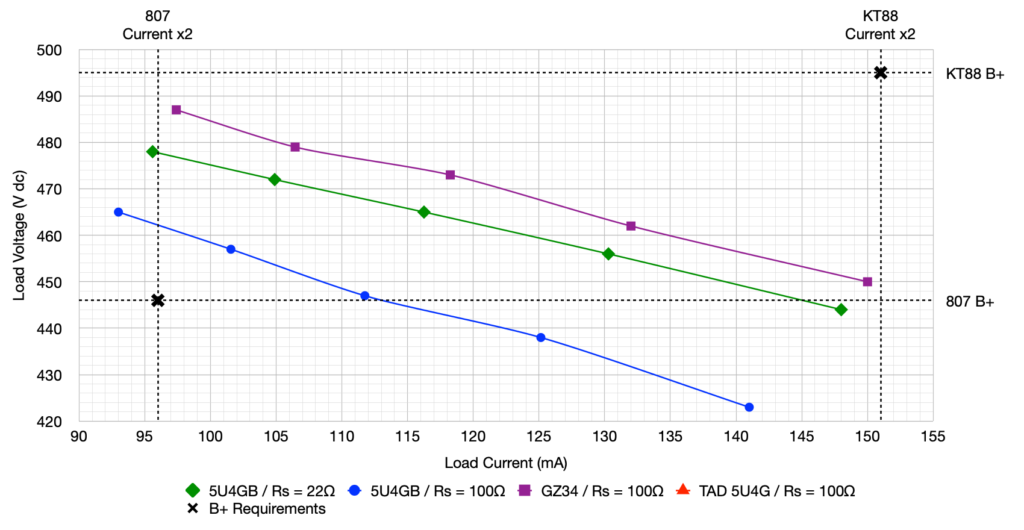
Each line in the graph shows how the power supply voltage changes as the current load on the supply is increased. The data points were taken at fixed load resistances of 5.0kΩ, 4.5kΩ, 4.0kΩ, 3.5kΩ, and 3.0kΩ with load resistance decreasing as load current increases. I have also included the B+ requirements (for both voltage and current) for the two different amplifier configurations. The two amplifiers have B+ voltage requirements that only differ by about 50V. However, the current requirements are wildly different. The top line (in purple) represents the GZ34. The next line down (in green) is the 5U4GB with 22Ω Rs resistors installed. The third line (in blue) is the 5U4GB again but with the 100Ω Rs resistors installed.
It should be evident now why I said that this data clearly shows the path forward. At the current level required by the 807 amplifier, all three configurations provide ample B+ voltage. However, at the current level required by the KT88 amplifier even the GZ34 solution is about 50V too low. Clearly the XPWR011 transformer is not well suited to my KT88 design. It will however work very well with my 807 design. As such, I think that will be the next amplifier to get built. I have some unique ideas for the chassis for this amplifier but details of that will have to wait.
For anyone disappointed that I’m not going directly to the triode strapped KT88 build, please don’t despair. After looking over the data last night, and since I’ve already received the output transformers for the KT88 amplifier, I went ahead and ordered the Edcor XPWR077 – 900V@200mA CT, 6.3V@5A, & 5V@3A CT power transformer. The additional 50v-rms per plate should get me very close to the B+ requirements for that amp. The XPWR077 is the highest voltage power transformer in the standard Edcor product line. If I want anything higher voltage I’ll either have to have one custom wound by Edcor or go with a Hammond 700 series transformer.
Now that my decision has been made it’s time to get moving with the chassis design. As I hinted before, this chassis is going to be different from anything I’ve ever built before.
As always, questions and comments are welcome.