Why?
A reasonable question at this point is to ask why attempt to revive this headphone amp. After all, it was a pretty bad failure the first time, the recovery amp built on the larger chassis was an unqualified success, and it’s essentially the same circuit as last time. What’s the point? Why not try something different? The answer is simple. It has nothing to do with the amp itself and everything to do with failure, recovery, and learning from my mistakes. And so I will try again. I will see if I can do what I think I can and make the amp work properly after all.
And besides, the vaguely philosophical point about failure not withstanding, there is really nothing inherent in the chassis design that should keep the amp from working well. The initial failure was because I did not give enough thought and consideration to task at hand. I arrogantly assumed that as a professional Electrical Engineer I could not fail at such a task. What I should have thought was that I should not fail at such a task. Failure is always an option if you don’t pay attention. So, more humble then before, I’ll attempt to make this one work. And, of course, a nice little headphone amp for my desk at work would be nice to have.
The Layouts - A Different Approach
The basic problem with the first attempt using this chassis was poor layout. The inclusion of a vacuum tube rectifier in this small chassis as well as the failure to isolate the high voltage AC from the signals led to excessive crosstalk and unacceptable hum. For the rebuild I decided to avoid these problems by first using solid state rectifier diodes and by isolating the power supply electronics from the amplifier circuits. Here is the layout for the major components on the top plate.
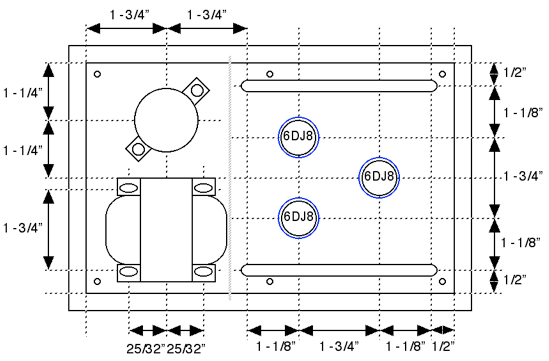
The only apparent difference is that there are now the three amp tubes instead of four. The rectifier has been replaced by solid state diodes inside the chassis. Also, the light gray bar to the right of the power transformer represents a metal shield inside the chassis to separate the signals. It’s still the same 5” x 8” plate so this amp has a very similar appearance to its first incarnation. The real differences become apparent when looking at the internal configuration.
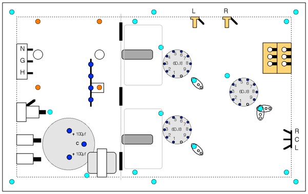
The most striking change is obviously the metal divider. This provides not only an internal shield but also now provides another mounting surface for the two output capacitors. This is still a very small chassis, but this is a much cleaner layout than before.
The Power Supply
The power supply design is very similar to that used before The only real difference is the use of solid state diodes, increasing the capacitor size to 100µF and a different resistor to set the operating voltage. This schematic is shown below.
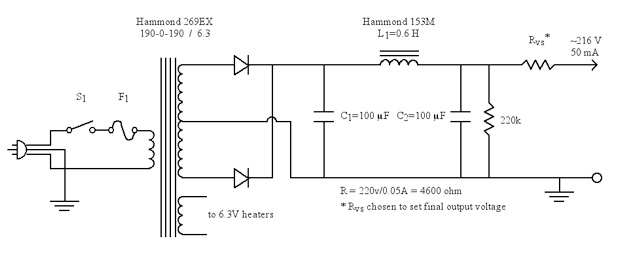
The inductor is undersized for this power supply load. It should really be above 4H but this is the only one I had on hand. In order to prevent inductor voltage runaway I have a B+ switch in the amp that can be seen in the photograph below. This means that the amp needs to be powered up with the B+ switch left off and then powered down with the B+ switch left on. A minor inconvenience. If it gets to be a problem, I’ll replace the inductor with a resistor and maybe add another cap after Rvs.
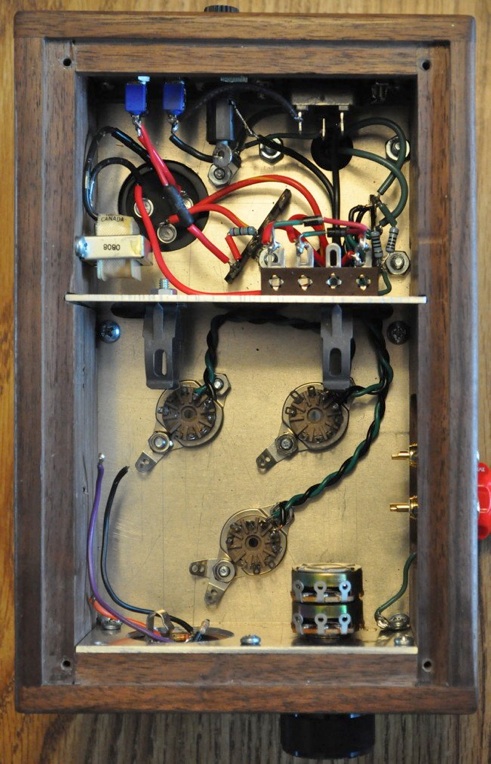
In this picture, the power supply is completely wired and the tube filaments have been wired to each tube socket. Now the power supply and all of its high voltage hum is encased in its own metal shield. This design also places the signal amplification tube as far as possible from the power supply.
Fitting It All iIn The Chassis
The new chassis layout is far better then with what I originally started. However, it is still a very small chassis for everything I am trying to include. The two output tubes are still only 1-3/4” center to center and I still have to include those two enormous output capacitors. The photo below shows the amp after I have wired up the two identical output stages.
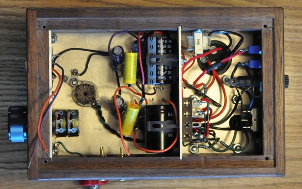
The two completed output stages take up just about all the space in the back half of the signal section. The orange and purple wires on the far left are the main output leads that have to be attached to the two large output capacitors. Those wires can’t even be connected until the input section of the amp is fully wired. Space is very tight indeed.
The Results
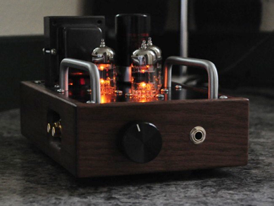
The finished amp sounds great. It finally operates the way it was intended. It is not as quiet as “The Recovery” amp, but I didn’t expect it to be in this small a chassis. At zero volume there is a very small, but still perceptible hum that disappears as soon as the music starts. Still, this amp will gain a special spot on my desk at work and will provide me with many hours of enjoyment in the coming years. This is a success!
What I Learned
Up at the top of this page when discussing why I should attempt to revive this amp, I mentioned learning from my mistakes. So this is probably a good point at which to summarize what I’ve learned from this experience.
The first thing I learned was about myself. There is a special type of apprehension surrounding tackling a project at which you failed the first time. Even though “The Recovery” amp was such a great success, I still was a little nervous about trying to make this one work. It would have been very easy to simply push the empty chassis to the back of some shelf and forget about it. By forcing myself to revisit this project and see it through to the end I learned to trust my skills and overcome the nervousness I felt throughout the project. And the payoff was a beautiful little headphone amp. As it sits on my work desk it will serve as a constant reminder to force myself to finish what I start and to not be afraid of initial failures.
I also learned a lot about point to point wiring with high voltages. This isn’t like working with modern solid state electronics. At work, avionics may have to be small and light, but in the vacuum tube world it’s OK to spread things out.
And finally I learned that there is no virtue in forcing myself to work in small boxes. I am convinced that I will never again build a tube project on such a small chassis. There is no need. At times, working on this amp was more of a chore then a relaxing past time simply because I was having trouble seeing what I was doing. And, above all else, I want to enjoy what I do. Life is simply too short to be frustrated when you don’t have to be.