Since I first introduced the concept for the “Universal Preamp” over ten years ago on the DIYAudioProjects forum, there has been almost constant discussion of my decision to place the volume control on the output of the preamp. I have been asked questions about it numerous times over the years. I have also had some “spirited discussions” with some who vehemently disagree with that design decision. Well, I thought it was high time to explain that decision once and for all, and to discuss exactly what this configuration means for preamp performance and output impedance.
The Universal Preamp “Origin” Story
First, a little background. The entire concept for the Universal Preamp arose from a forum thread in which the original poster was considering a simple preamp to provide some “warmth” to a system. He already had a schematic in mind and there was much discussion on the original design and many other options suggested. It was during these discussions when the proverbial gauntlet was thrown down with the following statement:
“In a future build … I may do a build which can switch from 12AU7 to 12AX7.”
It was with this prodding that the “Universal Preamp” was born. So the goal for the preamp was to provide some typical triode coloration to the sound and to allow for swapping different tubes without circuit changes.
Triode Distortion Characteristics and Design Decisions
To fully appreciate the topology of the preamp it is necessary to understand the distortion characteristics of triodes. When signal triodes are operated in a single ended configuration (such as the Universal Preamp) the distortion they produce is virtually all 2nd harmonic. In addition, the percentage of 2nd harmonic distortion is roughly proportional to the signal drive level. This means that as the signal increases, so does the proportion of 2nd harmonic distortion. If 200mV rms of input signal produces X% second harmonic then 400mV rms produces roughly 2X% second harmonic.
Now the 2nd harmonic is what is called the primary “Choral Harmonic”. Choral harmonics are the even order harmonics which provide warmth and fullness to sounds. So the goal of our design decisions should be to preserve these harmonics and to make sure that the levels are sufficient to provide the desired color. Since the triode in a single ended configuration already provides the tonal color, the design just needs to preserve that character.
Design Decisions and Control Placement
The key to the preservation of the even harmonics is to not attenuate the input to the tube. With a volume control set to 12 o’clock, or half way, the control provides about 20dB of attenuation (or a factor of 0.1) to the signal. This means that if the control is placed on the input, then the tonal color of the stage will be reduced by about 90%. Usually to a level that is inaudible in the final music. If the control is placed on the output then all the tonal color of the triode is preserved and the signal, already possessing all the color, can be attenuated to the desired level on the output.
This decision, to place the control on the output, preserves the desired tonal characteristics, but it is not without consequences. These consequences include a lower noise figure (i.e. less noise) for the preamp, a variable output impedance affecting control linearity and coupling losses, and potential impacts to the high frequency performance of a following stage.
Consequences of Output Side Volume Control Placement
Putting the control on the output lowers the noise figure of the preamp. This is simple physics. So from a noise perspective this is a good decision.
The second consideration is one of output impedance. The following figure is a simplified diagram showing the control as driven by the signal out of the preamp.
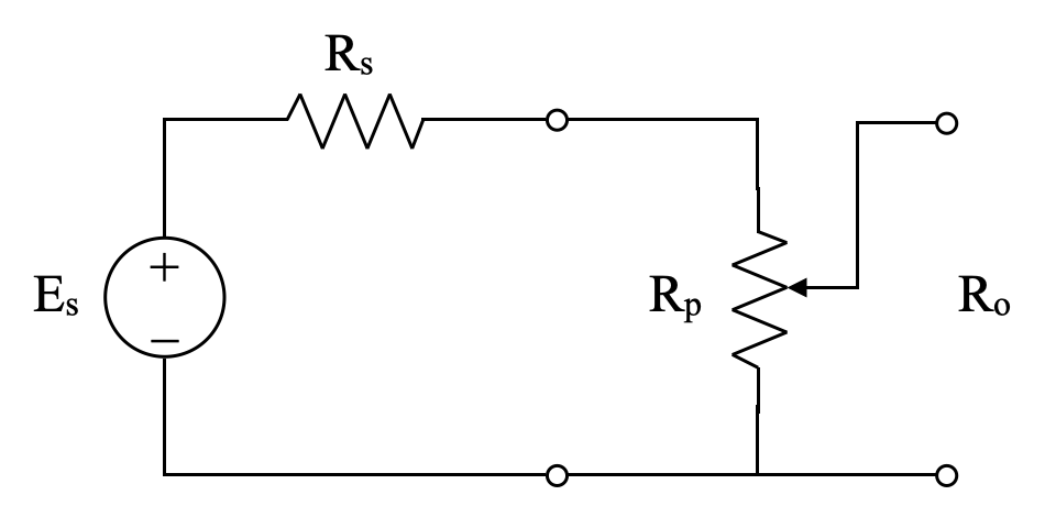
The Es voltage is the signal produced by the triode amplifier and the Rs resistance is the effective output impedance of the triode stage. The combination of the Es and Rs components is called a Thevenin Equivalent circuit. Using such equivalents greatly simplifies circuit analysis.
Visual inspection of the above figure shows that there is a portion of the volume control which is in series with the triode stage output impedance, Rs, and there is a portion which shunts the output to ground. This means that the combined output impedance is a parallel combination of Rs in series with the upper portion of the control, and the shunt portion of the control. This means that the output impedance of the preamp will vary with control setting.
This situation is further complicated by the fact that for linear “volume” control the potentiometer must have an exponential, or audio taper, transfer characteristic. The combination of the taper function and the variable voltage divider function can be difficult to visualize. Let’s start with the circuit values resulting from using the 12AU7 in the preamp circuit. In this case Rs is approximately 11.5kΩ and Rp is 250kΩ. Note that without the control on the output, the preamp output impedance would simply be 11.5kΩ. It is the placement of the control that complicates the situation. The following figure shows the combined preamp output impedance as a function of volume control position.
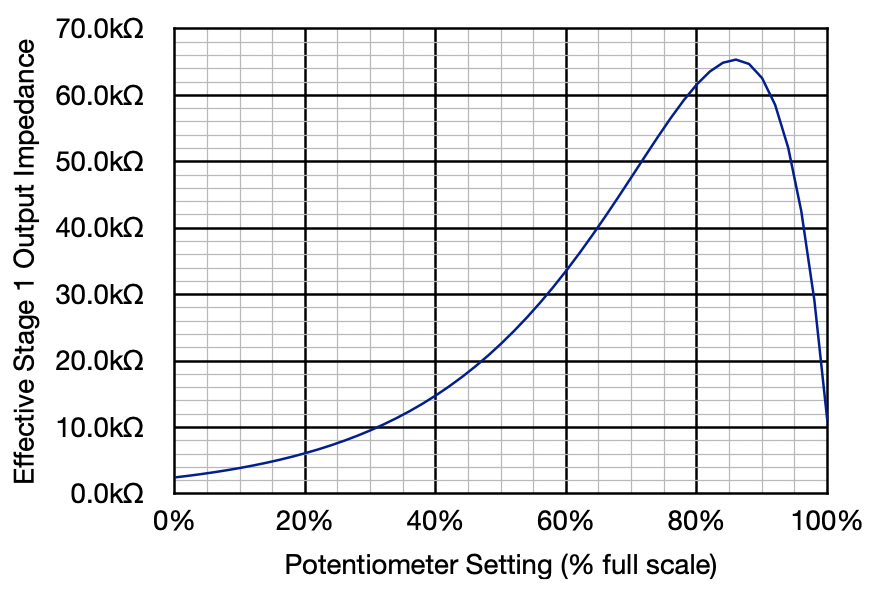
This curve starts relatively low but rises to about 65kΩ at 86% control position. Now the rule of thumb for impedances in voltage signal stages is that the output impedance of the driver stage should be not more than about 25% of the input impedance of the receiving stage. So strictly speaking, this preamp configuration should not be used on an amp with an input impedance lower than about 260kΩ. However, this condition only applies at that one setting. At the 50% setting the output impedance is closer to 23kΩ. Here our rule of thumb puts the required amp input impedance at only 92kΩ. It is informative to look at what happens when this rule is violated.
The rule in question (sometimes called the 4:1 impedance rule) was formulated to control voltage losses in cascaded stages. This 4:1 situation allows for approximately 2dB of attenuation in the output/input coupling due to impedance mismatch. The thought being that, since the whole point of cascaded stages is voltage amplification, the combined cascade should be designed to minimize losses. However, here we are talking about a specific stage to add adjustable gain to the system. It would seem, in this situation, that minimizing cascade losses is not a primary consideration.
Go back and consider the preamp with a 12AU7. This is the lowest gain option of all the possible tubes to be used in this preamp. With this tube, the Universal Preamp has an end to end gain of about 20dB (cathode unbypassed). When discussing control placement above, it was mentioned that a volume control set to 12 o’clock, or half way, provides about 20dB of attenuation (or a factor of 0.1) to the signal. This means that the preamp while using the 12AU7 provides signal attenuation with volume setting below half way, and signal gain with volume settings above half way. This means that the control setting range is approximately -20dB to +20dB.
If one were to use this configuration on an amplifier with a 100kΩ input impedance, the peak loss at 86% control setting would be about 10dB. However of that loss, about 9dB would be recovered in the last 4% of the control setting going to maximum. So the net effect is a minor deviation in the linear gain setting curve of the control. This is something about which most people would never need to worry. And if more gain is required earlier in the control range, moving to a slightly higher gain tube like a 12AV7 will provide it.
The other consideration is high frequency response due to the input capacitance of the amp to be driven. If the output impedance of the preamp is too large, then this can cause the upper frequency response corner to fall too low, suppressing high frequency response. Looking at the same preamp configuration above in combination with a power amp with an input impedance of 100kΩ and 50µµf is informative.
In this case the upper frequency response is satisfactory at most control settings. It is only the uppermost range where un undesirable result may be present. The following curve shows the upper frequency -3dB point verses control setting under these conditions.
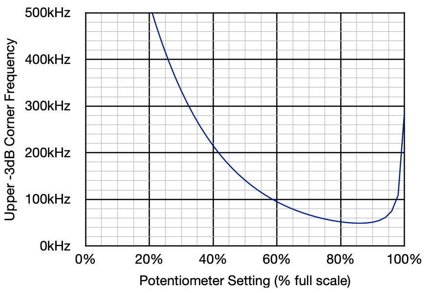
Here the upper frequency corner is well above the audio range and only falls to about 49kHz at the worst control setting. Using the higher gain tubes lowers this frequency a small amount, but even with the 12AX7 it is still well above the audio range.
Conclusion
I hope that this finally answers the question about placing the volume control on the Universal Preamp output. This configuration should be acceptable for use with almost any vacuum tube power amp with an input impedance of approximately 100kΩ or more.
As always, questions and comments are welcome.
Part II of this discussion can be found at this link: About that Volume Control - Part II