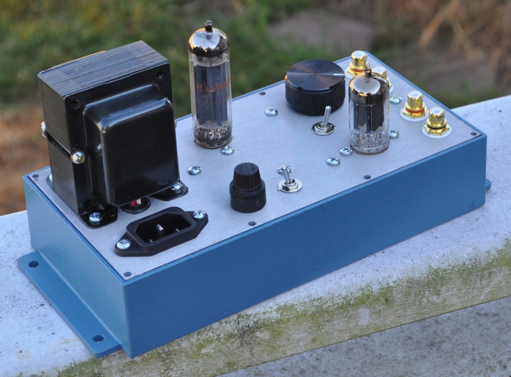
The basis for this amp started out as a post in a thread on the DIY Audio Projects Forum site. One of the members had suggested building a Super Simple Single Stage Preamp (“4S” Preamp for short) and there was much discussion concerning various tubes, gain, noise, etc. and several designs were presented using various dual triode tubes. Then the proverbial gauntlet was thrown down with the phrase “switch from 12AU7 to 12AX7”. My answer was to design a universal stage that would work well with an entire range of tubes. Thus was the 4S “Universal” preamp born.
The Electrical Design
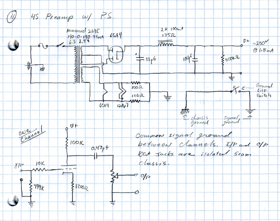
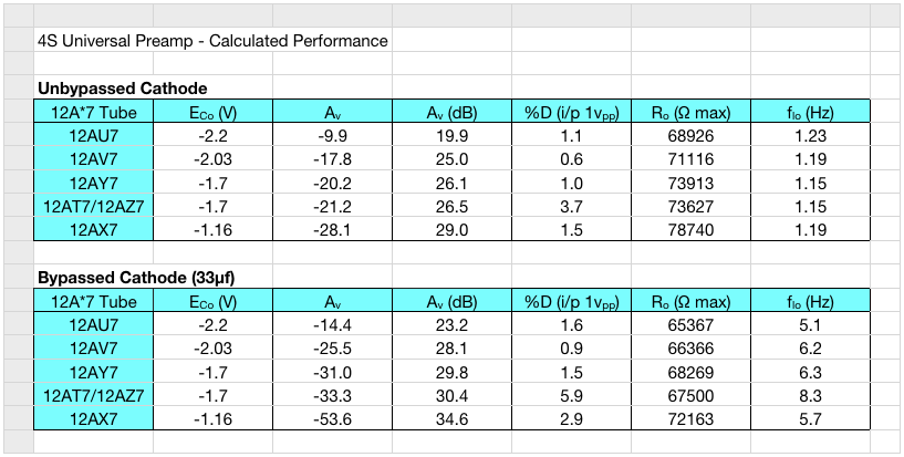
The design I came up with is a single circuit that can handle the following tubes with no changes: 12AU7, 12AV7, 12AY7, 12AT7, 12AZ7, and 12AX7. Dependent on the tube used (all these have the same pinout) and whether the cathode is bypassed, the peak gain may be varied by a large margin. Here is the circuit I implemented along with the tube rectified power supply.
The Build
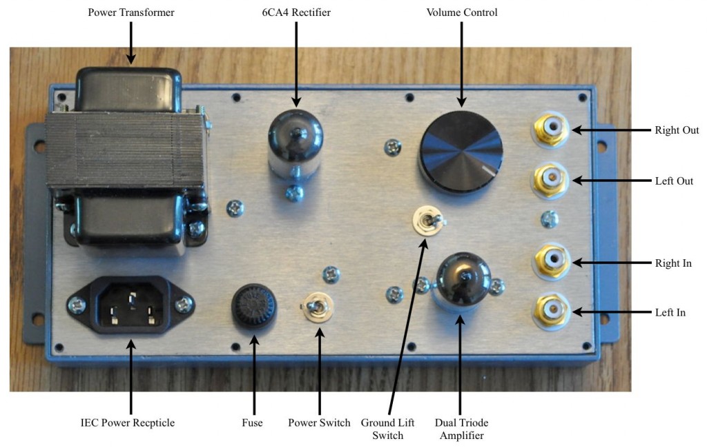
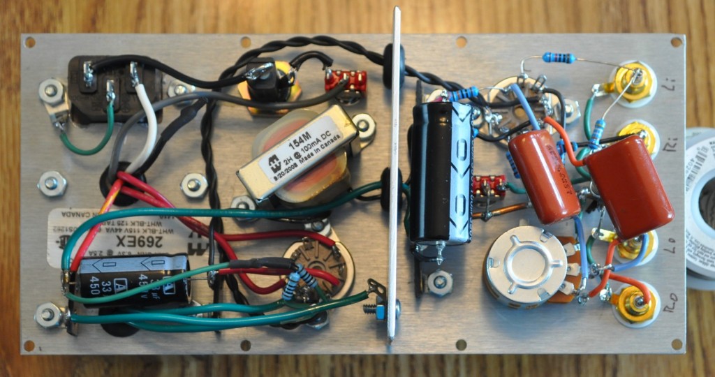
Deciding on the physical layout and build actually took some time. Up to this point, most of my tube builds have followed a fairly predictable pattern: wood base, aluminum top plate, polished finish, etc. For this build I wanted to go for two major themes: Utility & Compactness. So I started with a stock enclosure from Pomona, the 4226. This is an “E” size (8.3" x 4.2" x 1.74") die cast aluminum enclosure with a sheet aluminum cover and internal card guides. Although small, I was sure I could fit the entire PS and stereo preamp in this box. Instead of trying to run wires from the top plate to components mounted inside (which would make working on the box and sealing it up problematic) I decided to mount all of the components to the top plate. Then I could build the entire amp and when complete, just slide it into the box. Here is the layout for the major elements:
The Testing
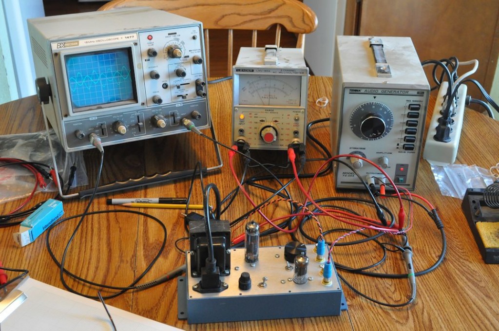
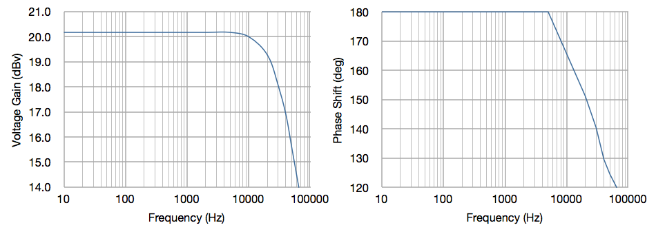
Testing a device of this type is really fairly straight forward. The first step is to simply power up the unit and check all the major voltage points in the circuit. This is done with the unit open and sitting on a workbench. For this build all voltages were as calculated to within a reasonable margin of error. For this type of device I like to test using a signal generator with adjustable output, a dual channel AC volt meter, and an oscilloscope. Here is a picture of the unit as I was running it through its paces.
Impressions
Of course, all this test data is nice, but it really doesn’t say much about how the preamp works and sounds. So once the unit was deemed technically acceptable, it was time to determine if it was sonically acceptable. This entailed hooking up the preamp to one of my other units. I chose the 6V6 Lacewood amp.
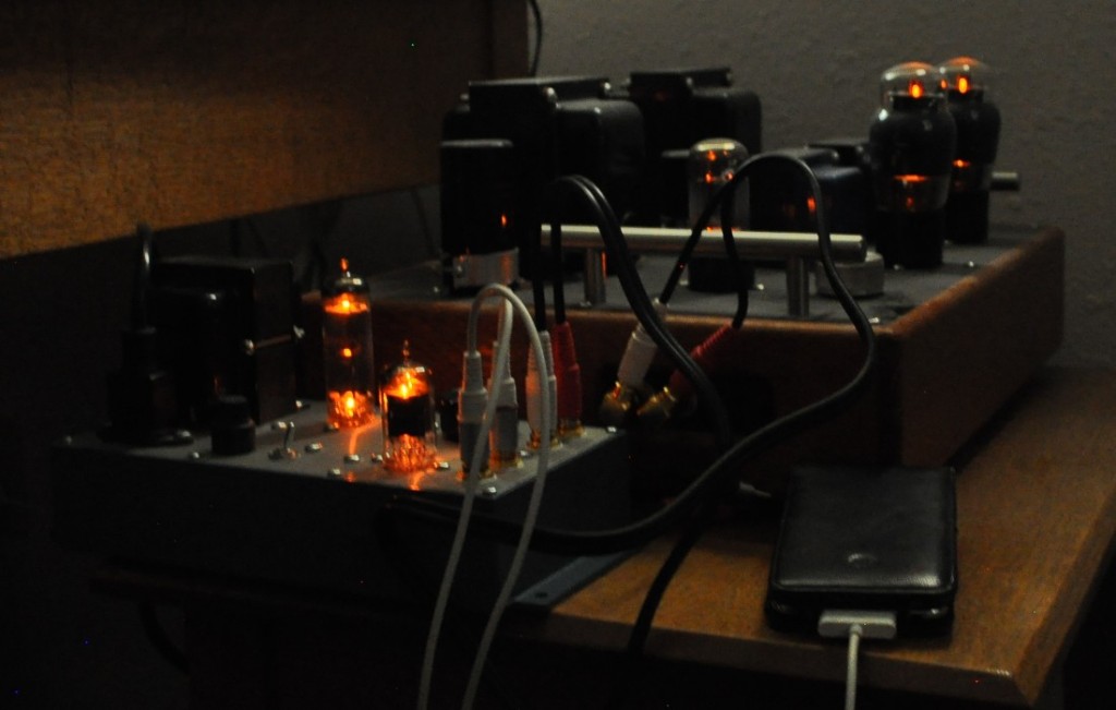
In the past, when driving this amp with just my iPod, I was disappointed with the overall performance. Not with the sound mind you, but with the attainable power level from the amp. The iPod output simply wasn’t enough to drive it to full power. So I inserted the preamp in front of the amp, turned the amp volume to max, and used the preamp control to adjust volume. Here is a picture of the setup.
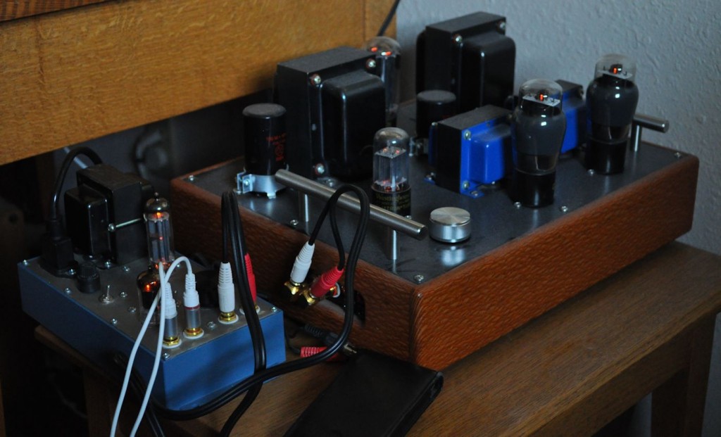
From the first moment I started playing music I was amazed at how the pair sounded together. There was absolutely no problem with signal level or power. And the added effective dynamic range really let the amp open up.
This project was a great success. I now have a preamp that can be adapted to the task at hand simply by swapping tubes. It also allows me to do some tube rolling to compare various tubes in my stash. And it can be configured with sufficient gain to test almost all of my prototype power stages. I think this little unit is going to see a lot of use.
On one other note, like all my other tube gear, it looks pretty good in the dark as well.
Update 17 January 2022: I have made a blog post discussing the placement of the volume control on the output and the consequences of this decision. It may be found at the following link: /2022/01/17/about-that-volume-control/
Update 18 January 2022: I have added this link to my Grounding philosophy so that builders fully understand the purpose and usage of the Ground Lift Switch. It may be found at the following link: /2020/01/13/grounding-philosophy/
Note 1 July 2022: If driving a solid state amplifier, the output impedance of the 4S Universal may be too large. In these instances the 12AU7 Color Preamp is another option for driving solid state amplifiers. The 12AU7 color preamp has a low enough output impedance to properly drive most solid state amplifiers and provides a line level adjustment of -20dB to +20dB.