So I decided today that I really needed to close the book on the color preamp. This means that I couldn’t just prototype a new buffer and leave it at that. The preamp needed an end-to-end test in it’s final design configuration. So that’s what I did. The results were even better than before.
So if I were going to make this happen, I needed to open up the preamp and make some changes. The buffer load resistors would need to change and the -6dB pad I put on the input would have to come out. Also, the volume knob needed to be realigned. So here are the hardware changes I made in the chassis. First, came the new buffer load resistors.
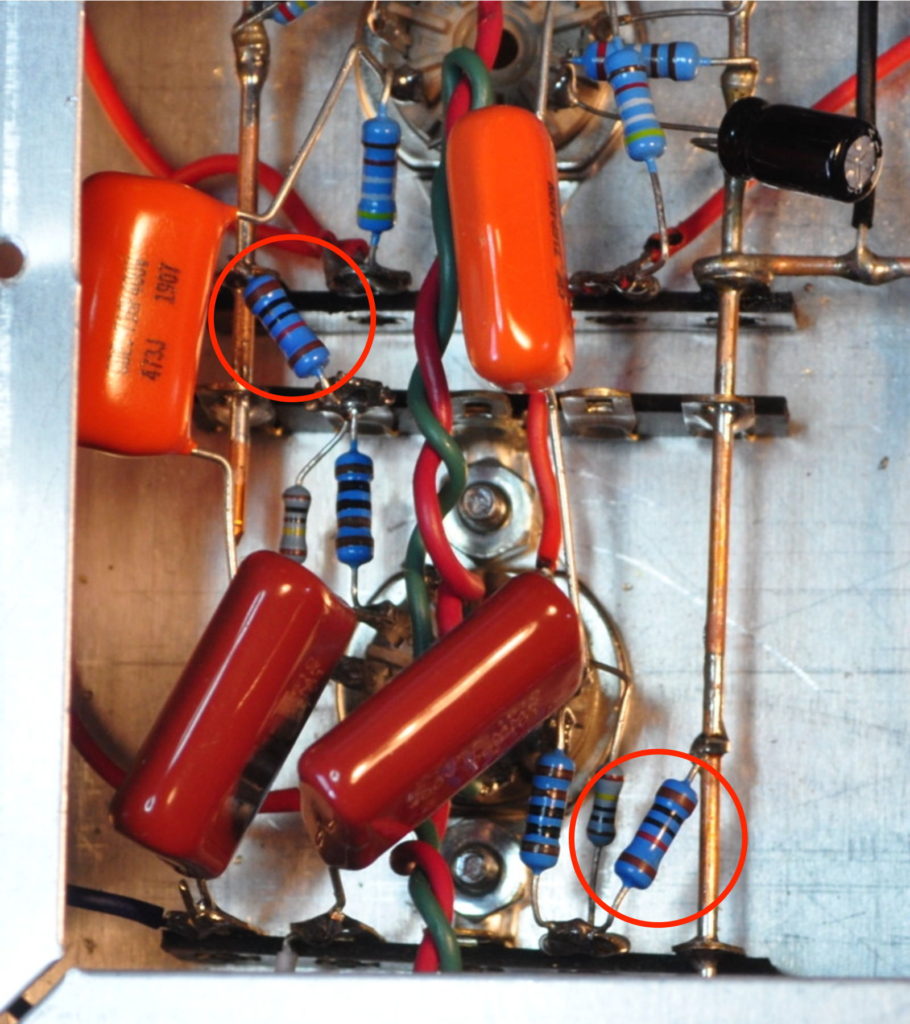
You can see them here circled in red. Working in this chassis was still not easy. Those really are some cramped spaces for soldering in new parts. The other major change was the removal of the pads in the input connection.
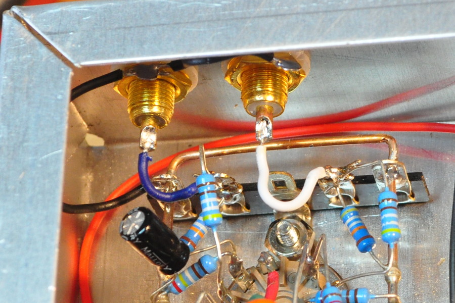
In this picture you can see the resistors removed and the input wires back in place. It was good to get the pad out of the circuit. The additional 500kΩ in the signal line seriously hindered the high end response. With those resistors gone, the original gain stage bandpass performance has returned.
One change which I made on the schematic but did not implement in the prototype was new coupling capacitors. On the revised schematic I increased these capacitors to 0.1µf because I wanted a little better low end performance. But the change is only about 1dB at 20Hz so I decided to leave the 0.047µf coupling capacitors in place. It’s always best to change as few things at a time as possible and I really wanted to assess the new buffer performance.
As before I did a quick spot check at three drive voltage conditions at a frequency of nominally 1kHz. Here are the results for both channels.
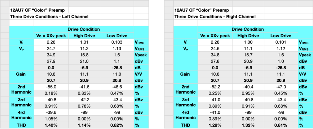
The high drive condition is 7.1dBv or about +9dBu. That’s a very stout signal. No line level source should ever go this high. And this was the point where the buffer just started to compress so I consider this a good representative maximum drive condition. The preamp can handle larger signals but the harmonic structure will begin to look more “transistor like”. You’ll also note that the stage gain is back at about 21dB. This means that the volume control at 50% is about 0dB and the total range of the volume control is a nice symmetric +/- 20dB. This feature alone makes this a very nice way to balance sources and amplifiers.
The bandpass of the preamp is about what one would expect. Here are the gain and phase plots.
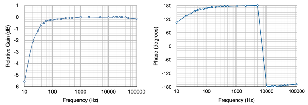
At the low frequency end, the amp rolls off gently starting about 50Hz. The gain is down ≈0.7dB at 40Hz, ≈1.2dB at 30Hz, and ≈2.1dB at 20Hz. At the high frequency end, the Miller capacitance doesn’t start kicking in until the frequency gets above 50kHz. The change of the coupling capacitors from 0.047µf to 0.10µf should help regain about a dB at 20Hz more or less. But frankly, this response is good enough as is that there really wasn’t any need for me to make the change in the prototype.
The last test was a listening test with the same class-d amplifier and speakers from before. The result was even better than last time. Frankly, I was shocked at the difference the improved buffer and the lack of pad made in how this little unit sounds. It takes a sterile sounding system and adds both warmth and depth. The preamp does exactly what I wanted. I very happy with the results.
This wraps up this little diversion project. This project effectively occupied the entire month of February. And even though the snow has returned this morning with 28°F (-2°C) temperatures, I feel like I really need to get back to the 6AS7 SET project. I’m not quite sure how I’m going to do that yet, but I’ll figure something out.
As always, question and comments are welcome.