There are a variety of sayings, axioms, proverbs, or quips which could apply to me this afternoon. A few which come to mind include:
“How wayward the decrees of fate are” - Vanitas Vanitatum - William Makepeace Thackeray
or this one:
“Pride goeth before destruction, and an haughty spirit before a fall” - Proverbs 16:18
or just the simple axiom:
“It ain’t over till it’s over” - Yogi Berra
In any event, it would seem that “Final Chapter” or no, I have one more post concerning the Color Preamp.
After the post yesterday I was going through my notes and something struck me. When working on the alternate buffer prototype, I varied the B+ voltage and made some assessments. I decided, and stated so in my improved buffer post, that the B+ should not be allowed to go below 285vdc for proper operation. I then realized that I never reevaluated the value of Rd with the new buffer design. The new buffer draws considerably more current that the previous version; 7.7mA versus 3.7mA or twice as much. This was something that needed to be checked.
So I opened up the prototype preamp and checked the B+ voltage; it was 254vdc. So out came the soldering iron and I went to work. I removed the old 4kΩ Rd, did a few calculations, and tested a few different values of dropping resistor trying to get close to the 300v target voltage. Here’s the prototype on my work bench this morning.
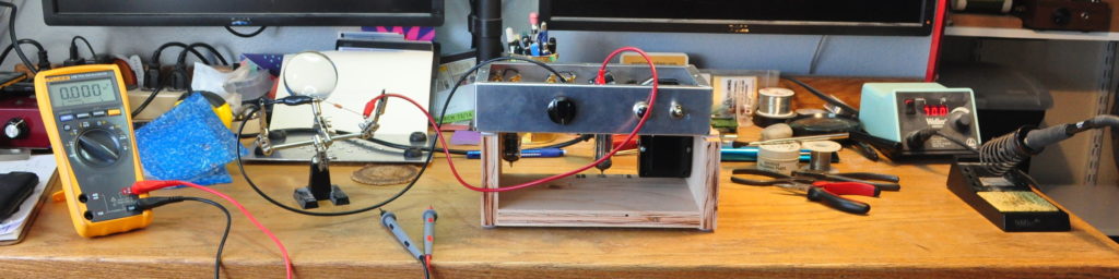
That’s the new Rd perched between the alligator clips of my work jig. I took the picture after powering down. I’m just not comfortable leaving setups like this powered up if I’m moving around doing other things. Subsequent to the photo, I installed the new Rd in the preamp. It’s a 1kΩ 2W power resistor. This made the settled B+ come to 297vdc. Right where I wanted it.
Of course I could not let it end here. I had castigated readers that the B+ had to be above 285vdc and I could hardly not hold myself to the same standard. I could also not let performance data taken at a B+ of 254Vdc stand as is. As such, I dutifully got out the test equipment and retested the preamp with the new (and properly valued) B+ voltage. Here are the spot checks on both channels at 1kHz.
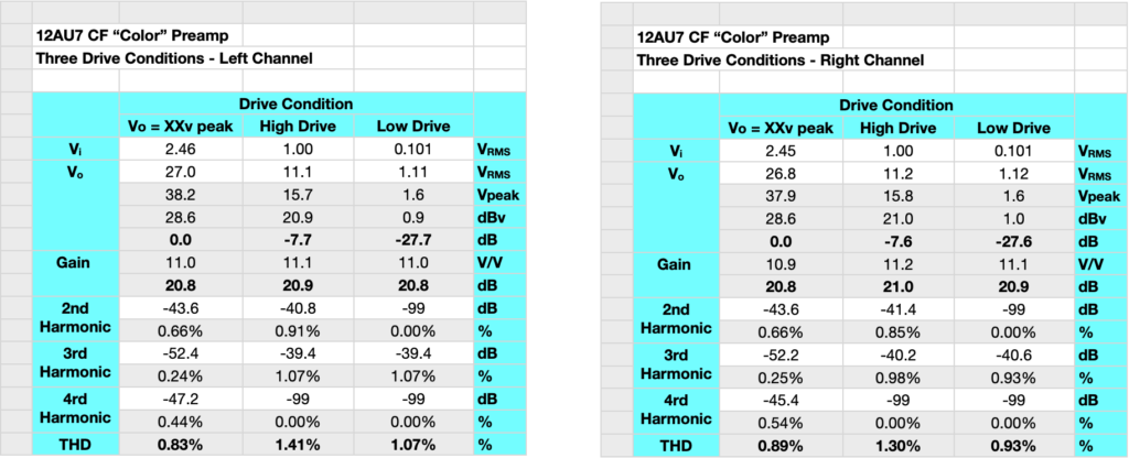
The gain in both channels is still just about 21dB. The input voltage before I started to see compression in the buffer increased a little. The max input voltage before the harmonics start to rise is 2.45v-rms or ≈3.5v peak. This is 7.8dBv or 10dBu. At these levels the preamp should be good to go for just about any line level source.
The bandpass and phase plots are much as before since none of the frequency dependent parts changed. Here are the new plots.
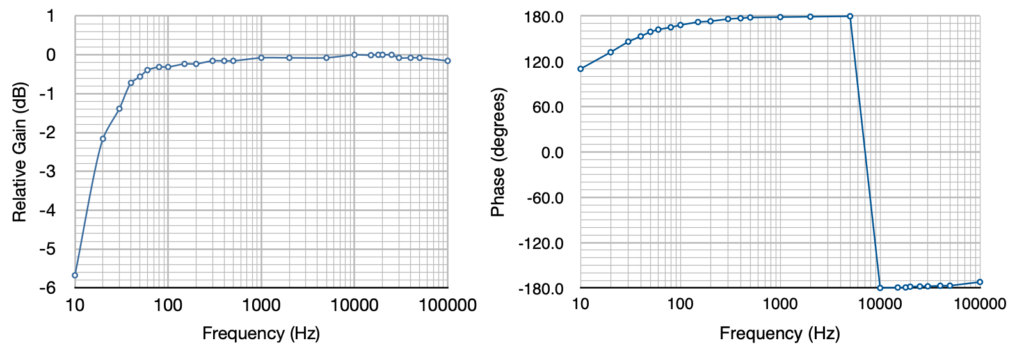
The amp is pretty flat at high frequency up until between 50kHz and 100kHz where Miller capacitance starts to take hold. The same gentle rolloff at low frequencies is present. The response is down ≈0.7dB at 40Hz, ≈1.4dB at 30Hz, and ≈2.2dB at 20Hz. This is a good and properly controlled response curve. For anyone curious about the values, here is the table with direct measurements and calculations.
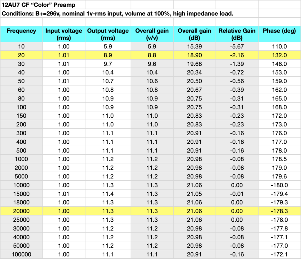
The minor variations in the pass band I directly attribute to the LSD values recorded in the table. As I’ve said many times “Real men don’t quibble over tenths of a dB”.
I am tempted now to actually state that I’m done with this project. However, as I don’t have any desire to tempt the Fates, I think I’ll just say that I’m done with this project for now.
As always, comments and questions are welcome.