It took a while but the DC checkout is complete and I’m finally ready to finish assembly on the Source Selector Unit.
The first step after receiving the dropping resistors was simply to remove a couple of wires and install the dropping resistor. This was actually the easy part. Here it is in place.
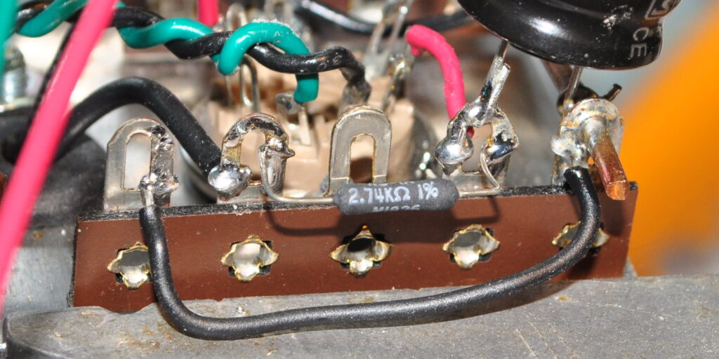
Although smaller than most of the dropping resistors I use, it was still a simple matter to solder this 2.74kΩ / 1W resistor into place. That’s when things got interesting.
When I started doing the DC checks I kept getting weird readings. First was mismatched buffer channels, so I swapped tubes. This fixed the buffer voltages, but things still didn’t look right in the gain stages. Here, the plate voltages were almost 60v too low and they weren’t stable. I could cycle power and then get different voltages. And the channels weren’t tracking each other.
So I thought maybe I had a bad tube. I tried three more 12AU7s of various pedigrees and vintages with similar, but slightly different, results. I have built at least a hundred different gain stages over the years and I’ve never had one behave this badly. Out of frustration I pulled the tubes and carefully checked every component value and connection. Everything checked out ok. So I reinstalled the tubes and tried again. Same result.
By this point I was more than a little frustrated with my little preamp, so I decided to take a break. While talking with my wife about how strange this circuit was behaving I sat and looked over at the assembly sitting on my work desk. With that one look I suddenly realized what was the problem. And it was me… all me.
You see, I decided that I wanted to do the DC checkout with the tube assembly in the clamping fixture. So I extended all the transformer leads to attach power the board. I didn’t need the input selector switch or volume control because this was only to be a DC checkout; no signal. And that’s where I was led astray. Here’s a picture for a hint.
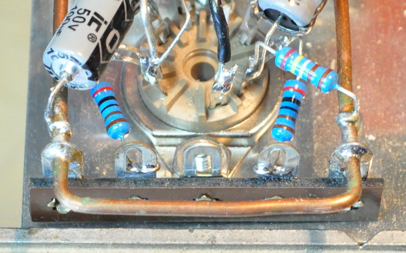
Those are the two 2kΩ grid stopper resistors on the inputs to the gain stages. Notice anything? They aren’t grounded. All the time I was testing, the grids of the gains stages were floating. In this design, the grid resistor function for the gain stages is provided by the resistance of the volume control. This is a good design when it’s all put together, but I had neglected to zero the inputs. As a result, the bias voltages were floating all over.
The solution was simple. I attached the wires I would use to tie the assembly to the volume control and grounded the ends. The temporary connections look like this.
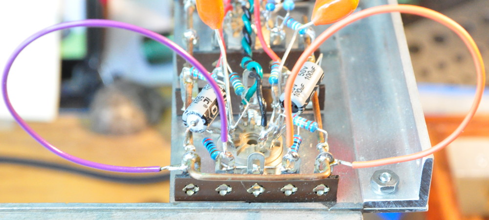
Needless to say, once I did this the entire circuit settled down considerably. And the voltages all came in acceptably close to the design points. Here are the measured voltages after this fix.
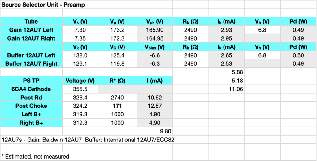
Now the gain stages are tracking each other and fairly close to the design points. Even with the B+ running about 6.5% high. The B+ is high because when I did the checkout for the Rd value, the inputs were floating and the gain triodes were drawing substantially more current. I could recalculate the value to get me closer to 300V but 6.5% high is really not that much. I’m comfortable with the operating points at this B+ voltage. When it comes time to install the unit I’ll clip the grounded end of those input wires and connect them to the volume control.
This is a good lesson about ALWAYS checking your assumptions. I really should have known better but I was so interested in pushing on, I just didn’t bother make sure all the inputs and outputs were properly terminated before proceeding. The output caps, which are installed on this assembly, were grounded through a pair of 500kΩ resistors, but the inputs were left floating.
I’d like to say I’ve learned my lesson. But I’m sure that this won’t be the last time my excitement about a project makes me skip steps. Now that the DC check out is complete and everything looks to be working properly, I can finally start the final assembly of the unit.
As always, questions and comments are welcome.