I’ve been making an effort this morning to get my head around the internal layout of the 6L6 SE-UL amplifier. Unfortunately, I keep being stymied by the sheer physical size of many of the components.
This all starts with the fact that, even though the power stage design is driven by the results of the 6L6 SE-UL optimization study, I am sizing the amp to be able to take the KT88/6550 power tubes with no modifications. I also am cognizant of the startup transient conditions which may let the B+ voltage level climb above steady state level by as much as 50v. So I decided that I needed electrolytic filter capacitors rated at 500V. I settled on ANH series capacitors made by JJ Electronics. This is where my problems started.
There are five of these filter capacitors in the amp; two 30µf and three 100µf. Each one is an axial leaded cylindrical package 1" (25.4mm) in diameter and about 1.65" (42mm) in length. When I put these into my layout drawing, they simply looked comically large in relation to everything else. Here’s the partial layout from this morning’s work.
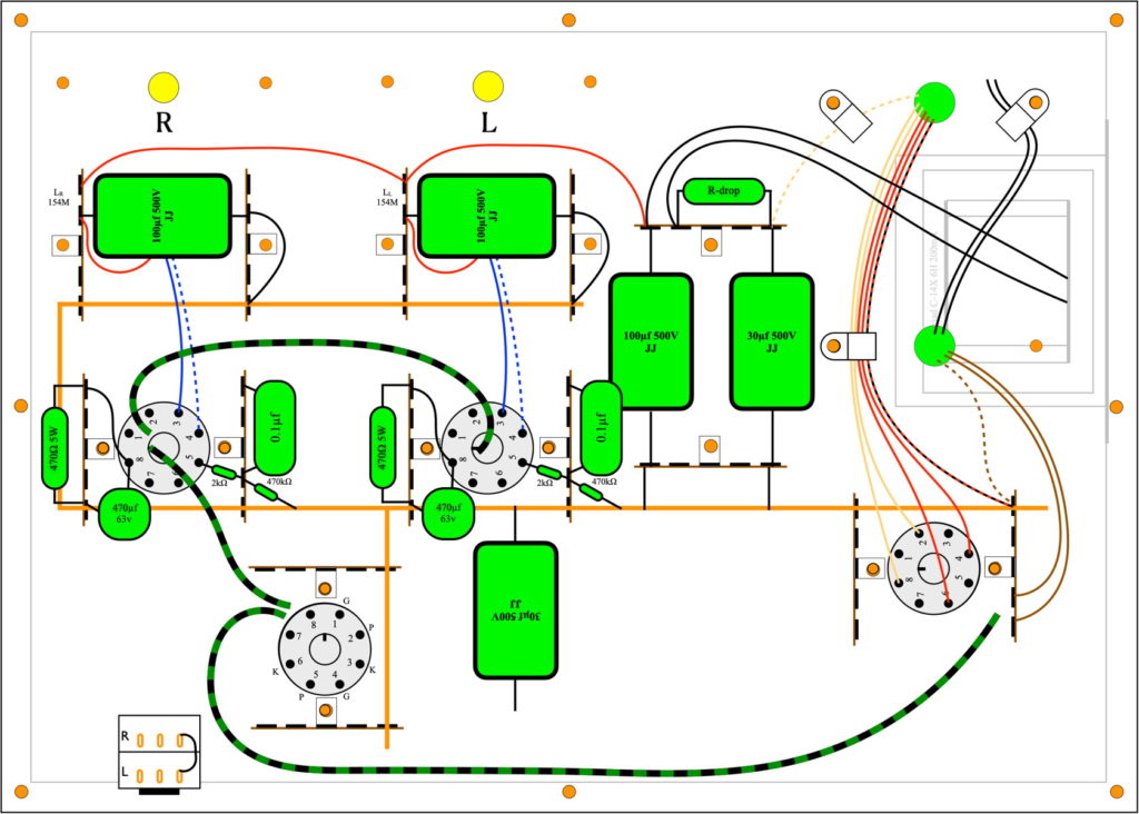
The big green rectangles are the filter capacitors. The top plate upon which everything is laid out is 14" x 10" (356mm x 254mm). Then I added the main filter choke, a Triad C-14X 6H open frame model, and it ate up a bunch of space. Even the coupling capacitors, CDE 716 Series 0.1µf 600v, are larger that I expected.
So now I’m to the point that every time I look at the layout drawing EVERYTHING looks comically large. I know this isn’t really the case. And I know that in the end everything will fit with space to spare. I just have to keep reminding myself that these layout drawings always look more crowded than the actual amps. If for no other reason than the two dimensional nature of the drawings.
Well, back to work.
As always, questions and comments are more than welcome.