Please read the post “That Didn’t Go Well!” before following the power supply change detailed in the later half of this post.
Sometimes a design which seems fine at first can later exhibit some marginal behavior. This exact issue recently reared its head with the design of the 6L6 “Spalted Alder” amplifier.
When I first started on the design of this amplifier, I did not prototype the power supply. Instead I looked at the design data and, based on my experience with the 6AS7 “Purpleheart” SET power supply, decided that the GZ34/5AR4 rectifier would work without problems. My oversight was in not noting the significantly higher rectifier plate voltages in the new design and taking appropriate precautions.
When first put into use, with the GZ34 rectifier I had on hand, the amp worked flawlessly. And continued to do so for many months. That’s when things started to go sideways. One evening the right 6L6 failed by arcing within the tube. It took a minute to notice and get across the room to shut down the amp. I replaced the tube, powered up the amp and everything seemed fine. The amp continued to operate apparently normally for a couple of more weeks, operating for five to six hours a day.
Then, after a couple of weeks, the GZ34 started to randomly arc at startup. Usually it was just one simple pop at startup and then the amp would function normally. I naturally assumed that the GZ34 was on it’s way out, so I ordered a replacement (I didn’t have any on hand) and inserted a 5U4GB until the replacement arrived. When I inserted the new GZ34 and powered up the amp, the new rectifier instantly started arcing and popping with a truly impressive internal light show. I immediately powered down the amp. This was going to require some investigation.
Upon opening up the amp, the first apparent problem was the 2H choke on the right channel power stage B+ filter. The choke showed significant discoloration. Here’s how it looked.
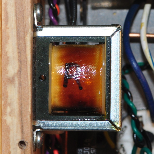
When I checked the choke it only measured a 6mH and had a series resistance of 6Ω. The choke had melted. I can only assume that this happened when the 6L6 failed by arcing over. Because the choke still had conductivity, the power stage could behave normally with just a little less B+ filtering. So the first step was replacing this choke.
The left channel choke also showed some signs of overheating but still checked out ok. I decided to leave it alone. This amp has had a series of tubes in it for testing and I don’t know if one of them was operating with significantly more plate current. I know that a couple of the used 6L6s I tried in the amp behaved poorly and were discarded. Here is the new choke installed.
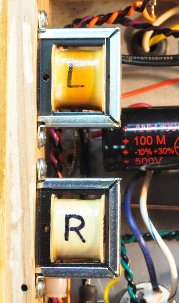
From this picture you can get a feel for the level of discoloration on the left channel filter choke. As I said, it shows signs of overheating but checked out within specification so I left it alone.
Following this repair, I meticulously checked every other component in the power supply. Everything checked out well within specification which left me in a quandary. The amp initially worked as designed and only had problems after tube failures. But I had repaired those failures and there was no reason that the shorted choke would cause problems with the new GZ34. So why had the new rectifier so quickly went to the great gig in the sky?
In an attempt to answer my question I went back to the specifications for the GZ34. The open circuit secondary voltage on the Edcor XPWR178 is about 350v per leg. According to the specification sheet, the recommended series plate resistance at this voltage is 105Ω with a 40µf first filter capacitor. My power supply uses a 30µf capacitor so this requirement could be slackened somewhat, but not a tremendous amount. The effective series resistance of the transformer by itself is only approximately 30Ω per leg. This is the genesis of my problems. Every other failure can be traced back to the blown 6L6 which obviously weakened the already stressed rectifier and the insufficient rectifier plate resistance.
So I needed 75Ω to get back to the recommended series resistance. I had available we some 75Ω/1W resistors. With the smaller first capacitor this will provide some additional protection and won’t cause more than a few volts of additional drop in the final supply B+ voltage.
So the transformer / rectifier wiring was modified to include these increased plate resistors. Heres how the new configuration looks.
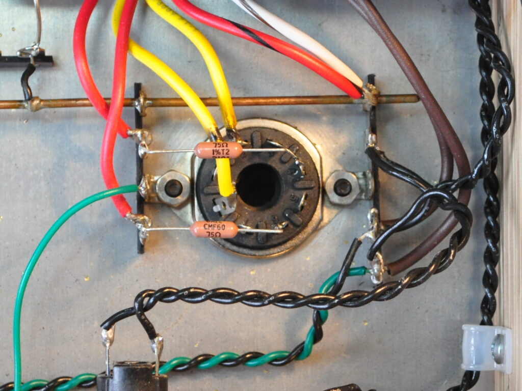
I simply moved the secondary leads over to a couple of open lugs on the terminal strip and inserted the two resistors between the terminal lugs and the rectifier socket. This is a simple wiring change which doesn’t even require any mechanical modifications.
I am recommending this change for anyone who has built (or is planning on building) this design. I have already made the necessary modifications to the main project page.
This whole episode serves to illustrate the pitfalls associated with the “build it and see” approach to design and build. I clearly made a major design error by not including the necessary rectifier plate resistance. This is an error I fully intend to avoid in the future. However, because, just by chance, I had a stronger than normal tube, the design worked for some time before problems became apparent. And now there are some other people out there with this very same issue. I feel bad about this.
So if you’ve built this amp please make this modification. In the future I’ll try to be a little more methodical in my design practices.
As always, questions and comments are welcome.