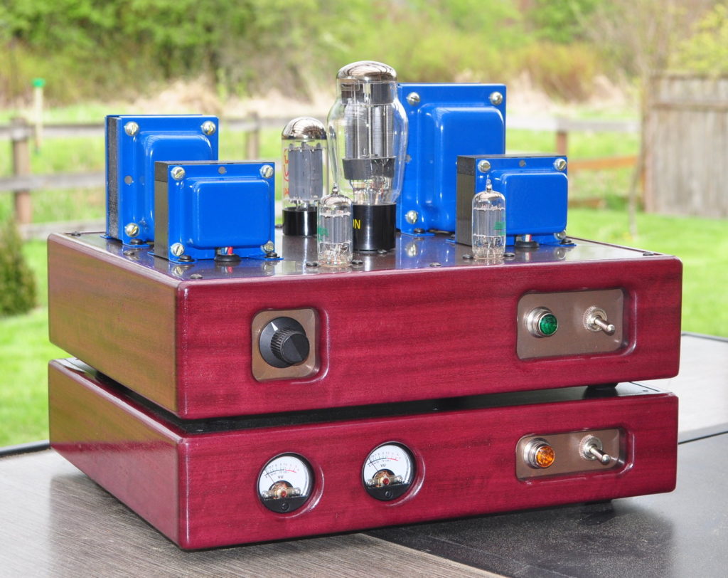
A Long Time in the Making
Ever since completing the 6336 SET back in 2017 this amp has been bouncing around in my head. The big SET has a lot going for it, however there is a high price to be paid in both amplifier infrastructure and operational heat. And that price is basically for a handful of dBs (≈4.4dB in the end) difference in peak power performance. I had developed a design for a 6AS7 SET driven by a 12AX7 several years before but was never happy with that design. However, once I developed the high voltage swing driver for the 6336 SET, it opened up all kinds of new possibilities.
Finally in the fall of 2020 I had decided that the time was ripe for the new SET. This was to be an amplifier that sits, in terms of power, right between the small SETs like the 6CY7 Zebrawood amp and the big 6336 SET amp. And after much investigation, I settled on the 6AS7 dual power triode. My calculations showed I should be able to get between two and three clean watts out of each triode and maybe up to four before the distortion got too bad.
Now, with decisions made for both the driver and the power tube, it was time to formalize the design and get going.
The Electrical Design
With the driver stage already throughly investigated for the 6336 SET, the design for this amp turned to the 6AS7 power triode. After investigating several different plate loads I settled on a 2.5kΩ load for each triode. This value presents a good compromise between power and distortion. Since this tube is rich in second harmonic character, I chose what I thought was a balanced bias point between conduction and cutoff. Here is my load line design for the power stage.
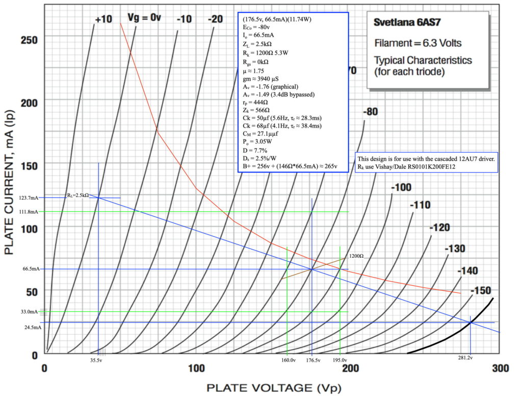
This design places the output power into the transformer at about three watts peak. Assuming an 80% transformer efficiency, this equates to about 2.4W peak power out. This was, I decided, a good design solution for the class of SET I wanted. This is not to say that the power output is limited to this, but this is the clean power out design point. It is entirely possible to drive the speakers up to about 4W before the odd order distortion becomes noticeable. This assumption has proven to be correct in initial auditions of the amplifier.
Although I already had the driver stage design, there were a couple of changes I wanted to make for this amp. These are all component changes to support the desired amplifier bandwidth. For reference, here is the final as-built amplifier and power supply schematic.
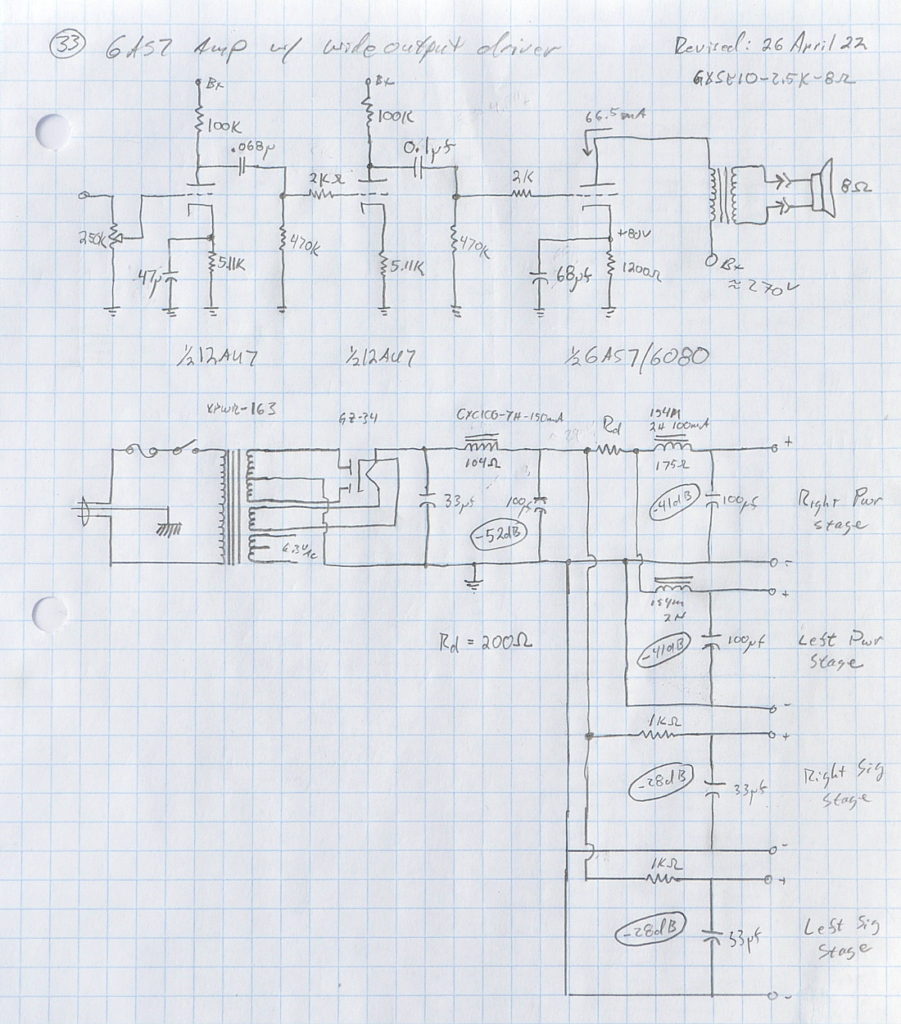
The changes to the driver were all capacitative changes. The danger in using too large a coupling or bypass capacitor lies in what happens when the grid goes into conduction. But since I had already determined that the driver can go to well over +/-90V peak, I knew that the the power stage would be the first to enter an overdrive condition. This makes only the second coupling cap in any way critical.
So for the driver for this amp, I increased the first stage bypass to 47µf and the first coupling capacitor to 0.068µf. I felt comfortable with a 68µf power stage bypass value as well. I had reason to believe that the power stage cathode impedance I calculated from the load line design was actually lower than calculated based on some prototyping work. This left only the last coupling capacitor. After running the calculations I decided to increase this capacitor to 0.1µf. This places the -3dB rolloff point at ≈2.8Hz with a recovery time constant of ≈56ms. This is normally a little longer than I’d like but the risk of blocking at over full power is relatively low.
With these decisions made and incorporated into the final schematic the, electrical design was complete.
The Build
The build for this amplifier followed a long and twisted road. It started with trying to choose wood from several different hardwood species. These are the five finalists:
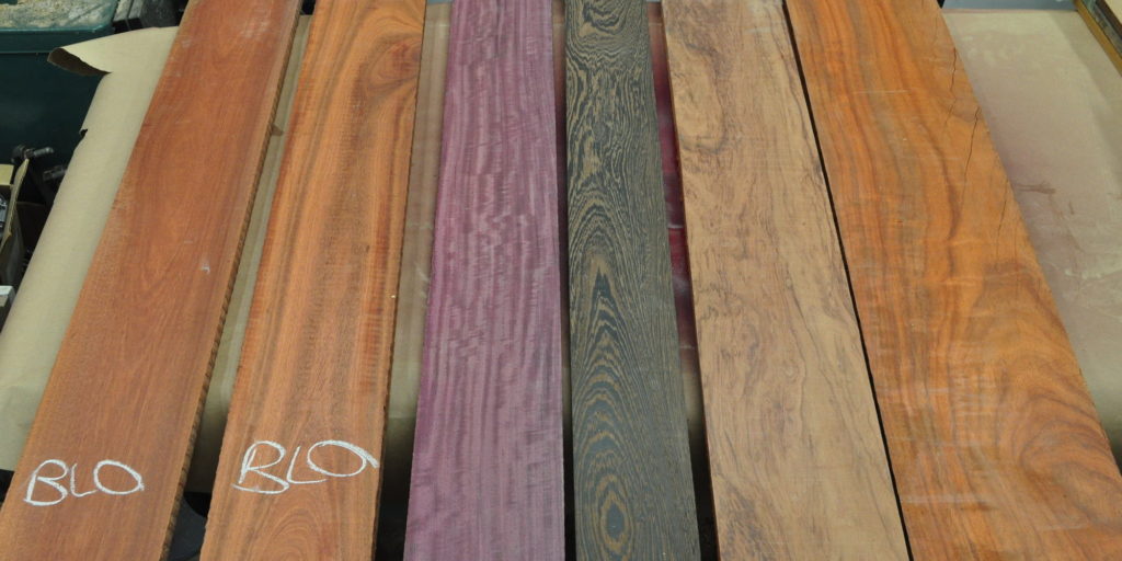
There are from left to right, Bloodwood (fine grain), Bloodwood (coarse grain), Purpleheart, Wenge, Bubinga, and Padauk. At the time I also had the idea that I should be using copper for the top and front plates. Having settled on the purpleheart, I began to give consideration to the copper. I finally decided that I was going to use an oil finish on the wood and use a tarnish patina on the copper. This decision led to a long series of investigations and experiments attempting to find the way to achieve the copper patina I wanted.
I also hadn’t decided on the top layout at this point. I kept going back and forth between symmetric and asymmetric designs. I finally decided on a nice symmetric design with rectifier and power tube on the midline of the amp. Here’s the top layout. This top plate is 12" (≈305mm) wide and 10" (≈254mm) deep.
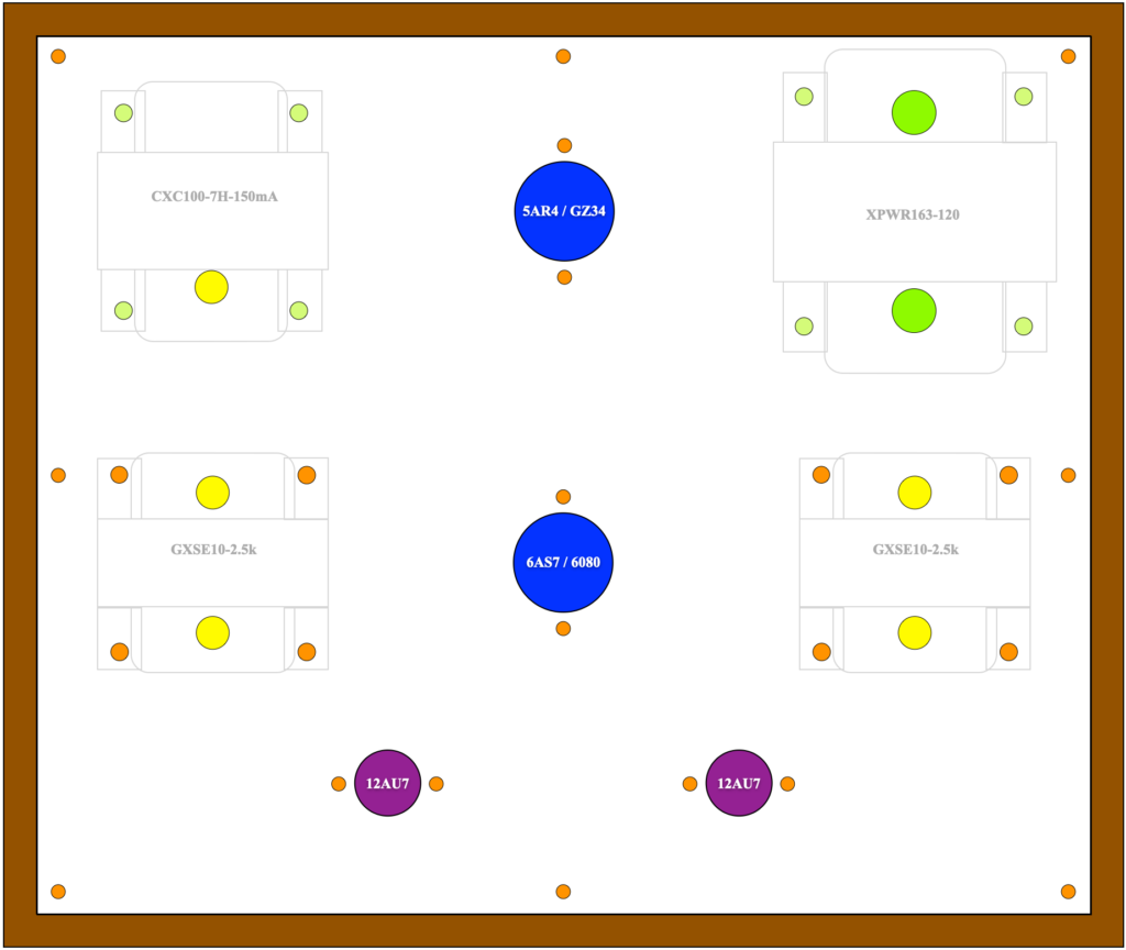
This layout gives ample separation for air flow on top and and ease of wiring beneath. I have a dimensioned diagram if anyone would like one.
The final decisions for the overall look and feel of the amplifier took considerably longer than any other decisions up to this point. After several months of twists, turns, and dead ends, I finally arrived at the look I wanted for the new amp. And it took me until March of this year to finally get it right. Here is the finished purpleheart chassis with the patina colored copper in place.
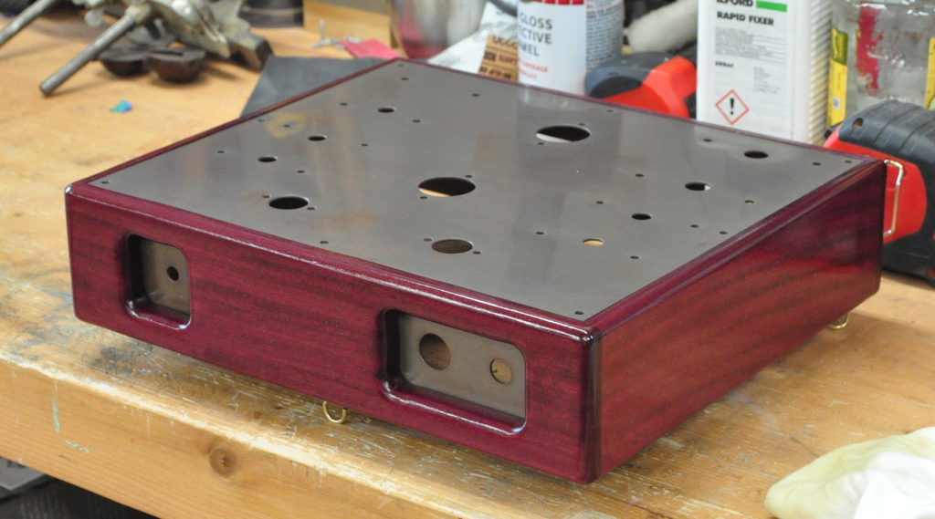
The picture really doesn’t do justice to the copper finish. It is beautifully aged just like it’s been in use for decades. With all the subtile variations one would expect from something that’s been around for quite a while.
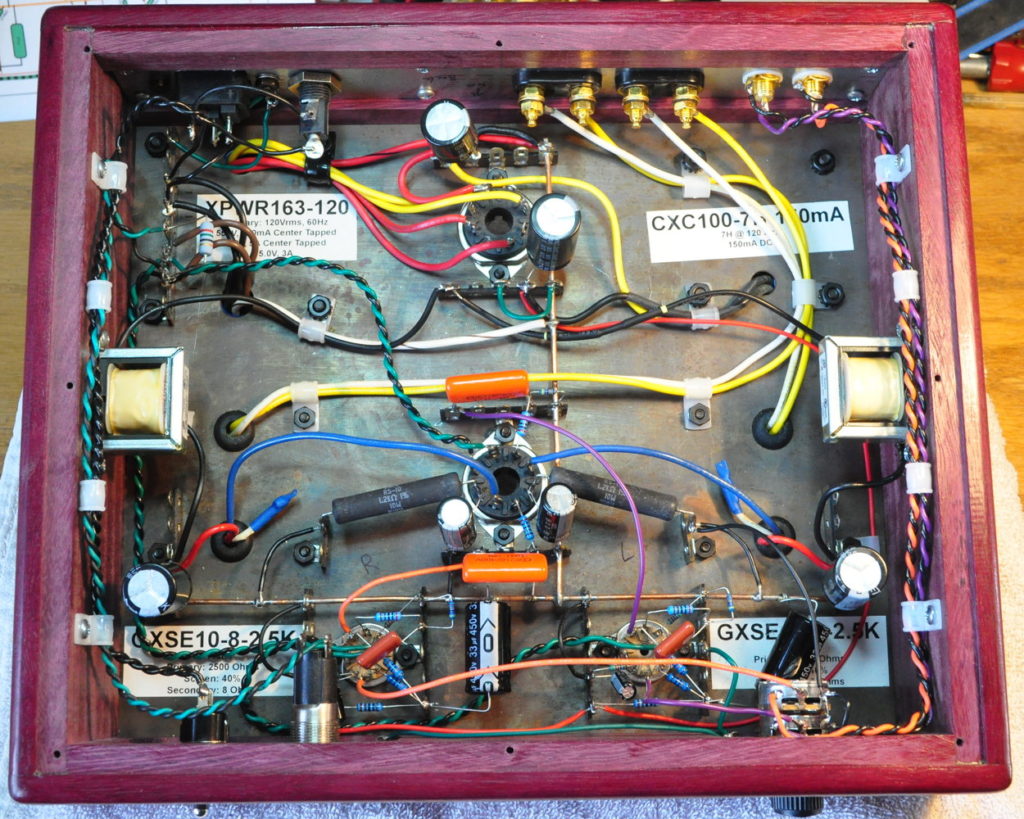
Once to this point assembly proceeded rather quickly. Here are the ring frame chassis with all the attached wiring, and the underside of the top plate with all the wiring and components in place.
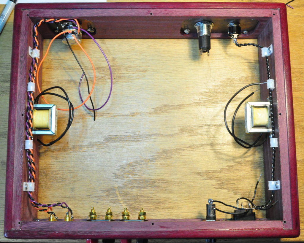
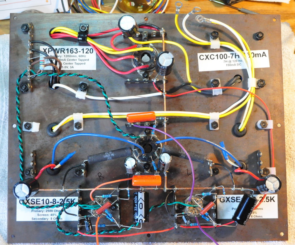
Once things had progressed to this point it was a simple matter to marry the top plate to the ring frame and connect up the remaining wiring. Here’s how it looked with everything except the final power supply dropping resistor in place.
The final step at this point is, after a final wiring check and an AC operation check without tubes, to install the tubes, apply power, and dial-in the B+ voltage. Here is the amp, sitting in a cradle, with a high power variable resistor temporarily wired into the power supply.
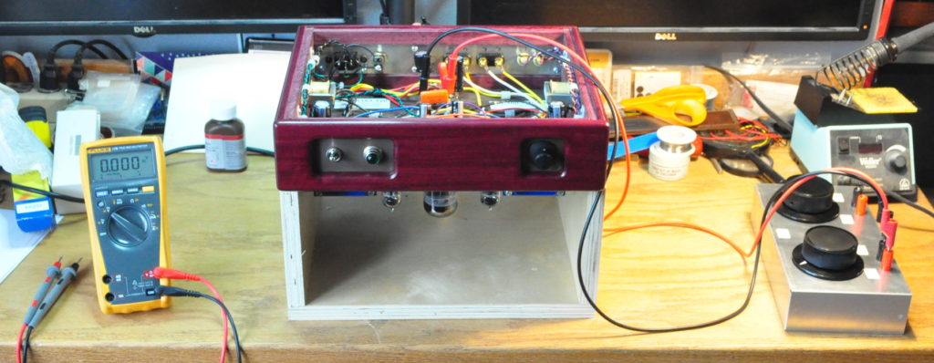
I dialed in the B+ voltage for the power stage. This required a 200Ω resistance to get the power stage voltages down to ≈267v. With this load for the power stages, the driver B+ voltages were 306v. This is a good operating spot for the cascaded drivers providing lots of clean swing to drive the plower triodes.
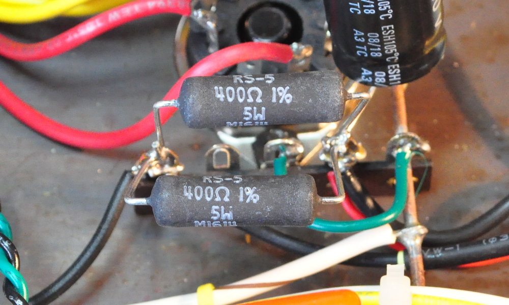
I didn’t have an appropriate 200Ω dropping resistor so I did what any good Engineer would do. I improvised. I did have in my stock a pair of 400Ω 1% wire-wound power resistors so I used them in parallel. Here they are installed in the amplifier.
The final act of assembly was to take a set of voltage readings in the final configuration to make sure everything is per design. Here are the measured bias voltages and operating conditions prior to installing the bottom plate on the amp.
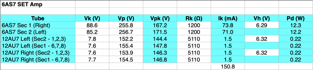
The power stage bias voltages are a little above the design point, but not enough to worry about. And the plate dissipations on the big triode are well within acceptable limits. The bias conditions on the drivers are also very close to the design points. At this point I closed up the amp and got ready to test.
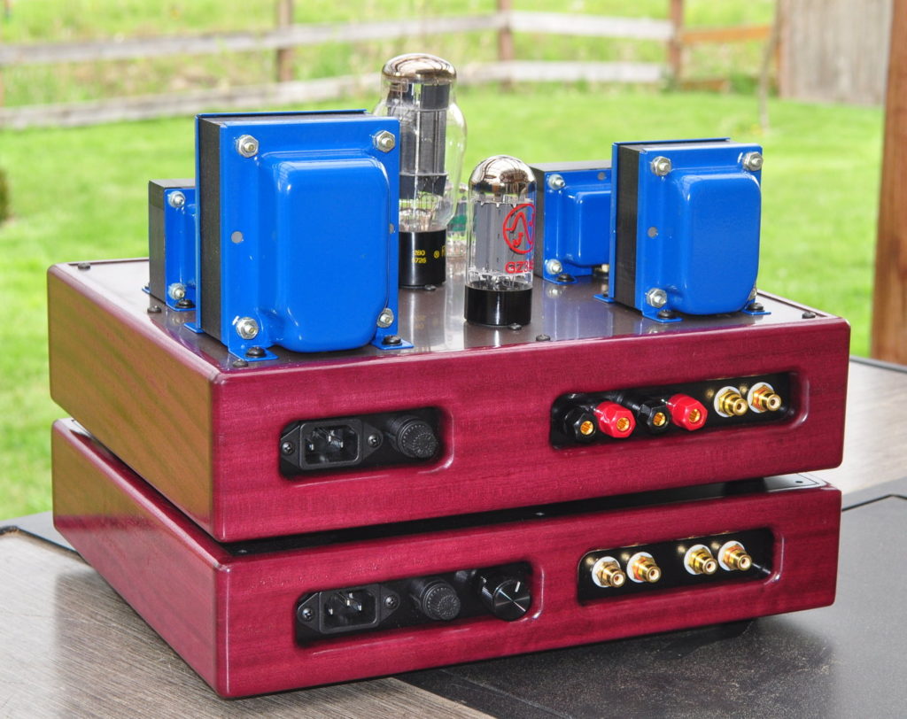
And here’s how it looks from the back showing the audio inputs and outputs and the power connection and fuse.
Initial Listening and Break-in
So I didn’t progress directly to testing. It was late in the afternoon when I finished so I plugged in the amp and let it fly. I was not disappointed! Over the course of about six hours I threw every type of music imaginable at this amp and it handled all of it flawlessly. From the very fast, to the slow, to deep bass, to crisp high frequencies, even harmonically difficult choral music and Gregorian chant sounded amazing. It was by far the best break-in session I have ever had with an amplifier.
Testing
The first step in testing was to determine the power and distortion characteristics for the amp. Here are the numbers for the first tube.
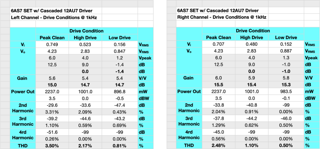
This data was with a JAN 6080 power tube in the amp. I chose this tube because I didn’t want to risk any of my older ST shaped 6AS7Gs until I was sure of the amp. The left channel distortion numbers were much higher than the right channel and the gain was noticeably lower. After swapping a couple of tubes, the left channel distortion numbers better aligned with the right channel and I moved forward.
I did not detect this difference auditorily during the initial listening and break-in. However I wanted better matched channels as I continued. One of the things I commented on in a post a while back was the variability of the examples of 6080s and 6AS7s I’ve seen. Using this tube it is probably a very good idea to try out several tubes to find the ones you like. I also may try a few new stock Svetlana 6AS7s to see if they are more uniform than the older tubes.
The peak numbers for power here are based on looking at waveforms on the oscilloscope and trying to detect asymmetries. However, I drove the amplifier to over 3.5W to get to the traditional 5% distortion number. But the distortion waveform had more odd harmonics than I generally prefer. Regardless, the amp sounds really good putting out between two and three watts.
The next step was the bandwidth check. When I started I was very hopeful because I had made several changes specifically to support a good amplifier bandwidth. As it turns out there was no reason for concern. The bandwidth of the amp is excellent. Here is the plot of end-to-end relative gain and phase for the amplifier.
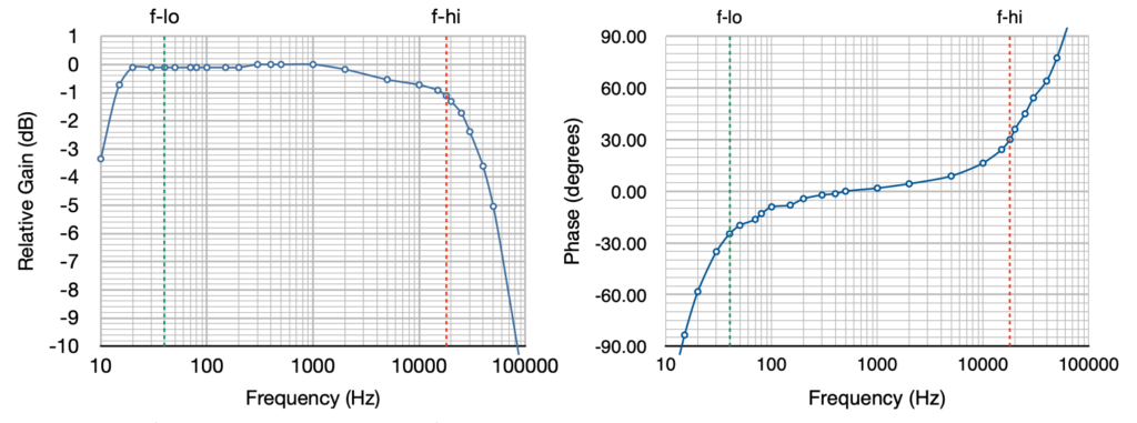
Due in no small part to the low Rp of the power triode and the changes I made to support the low end this amp goes down to 20Hz with essentially no falloff in performance. The response is down -0.11dB at 20Hz, -0.72dB at 15Hz, and -3.5dB at 10Hz. This is exceptionally good low end performance for a capacitively coupled vacuum tube amplifier. At the high end the amp is only down -1.31dB at 20 kHz. There is a gentle rolloff of about a 1.1dB between 1kHz and 18kHz due to the Miller capacitance of the power triode in combination with the exceptionally high output impedance of the unbypassed second driver stage. This was expected and as it’s only a dB, it is imperceptible in use. So the 1dB bandwidth of the amplifier is approximately 15Hz to 18kHz. This is GREAT performance.
Given the very good low end performance in the bandwidth, I decided to perform a low end distortion check as well. Many times, especially with beam power tubes in an SE-UL topology, the distortion at low frequencies can become rather large. But I wanted to see how this tube preformed with it’s low power tube plate resistance. Here is the distortion plot for the lower frequencies at 1W RMS mid-band power.
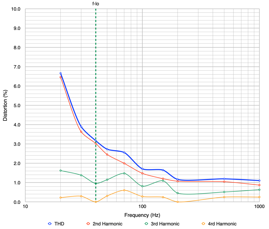
This is truly excellent low frequency performance and the 20Hz distortion number is less than half of what it is typically seen with SE-UL stages. Remember that these Edcor GXSE transformers are only rated to 40Hz. But these transformers clearly punch above their weight class.
These test results clearly show very capable amplifier. It has an output power rating just where I wanted it, it has good distortion characteristics, excellent bandwidth characteristics, and plenty of low end support. This is all great, but how does it sound?
Impressions
This amp sounds incredible! It has all the classic SET tonal characteristics but is also very fast and agile. And it delivers the low end with a power and presence that is exceptional. I mean “raises goose bumps” kind of exceptional.
As I said above, I threw just about every kind of music at this amp you could imagine. It never showed any signs of strain, distortion, or muddled sound at all. It was always clear and fast with that famous SET warmth and color.
I used Michala Petri’s recorder performance of “Frederick The Great : Sonata in B-Flat - Allegro” to test the amp’s speed and agility. It never missed a single beat of the very fast score and it was always as crisp and sharp as it is in person. To really test the low end I used Bachman-Turner Overdrive’s “Not Fragile - Quad Mix” off The Anthology album. This starts off with a strong bass riff that does not disappoint. Even over the other rhythm lines this strong bass comes through with great power and presence. I also used Norah Jones’s _“Cold Cold H_eart” off the “Come away with Me” album to see how the bass came through. This is another song with a strong ever present bass line. It never got lost or even a little muddy. It always came through smooth, crisp, and defined.
This amp makes me feel like I’m in the room with the musicians. The sound stage is wide and deep with excellent clarity.
Summary
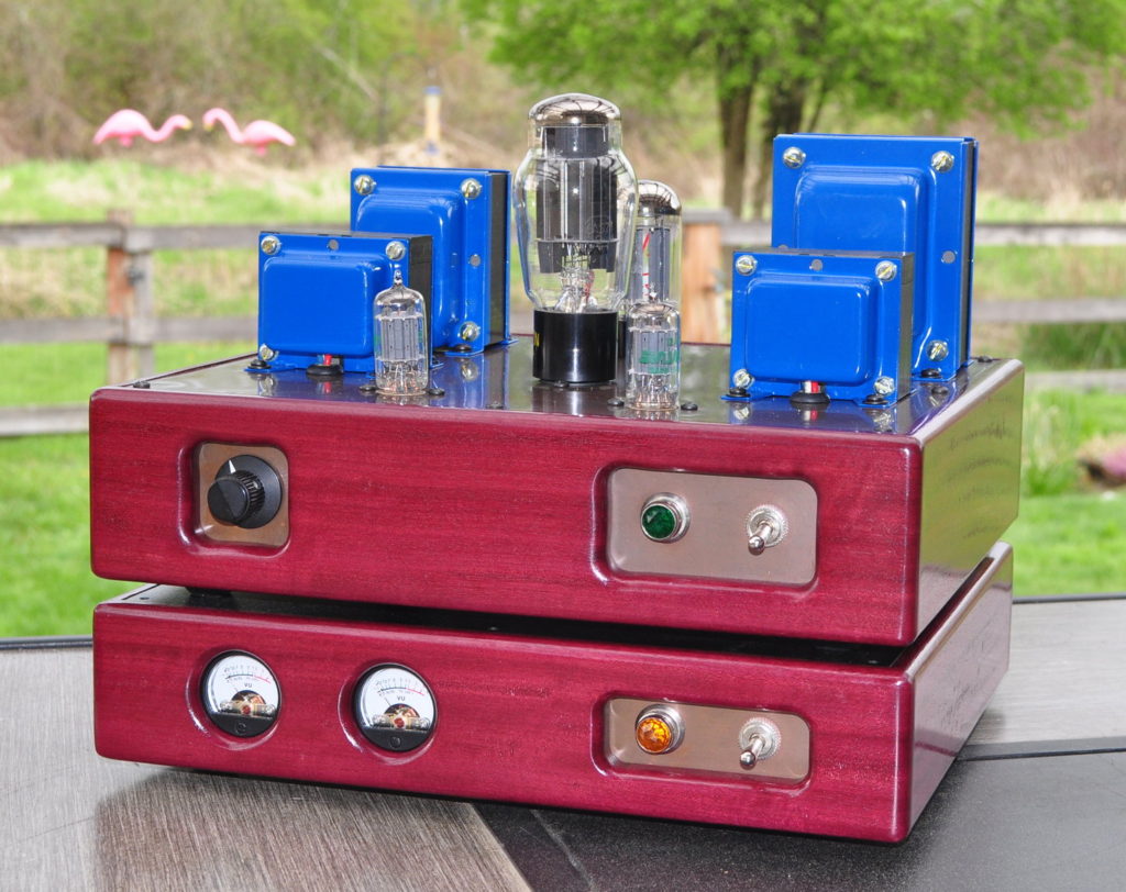
This amplifier is an unqualified success. It was well worth the 19 month journey from initial idea to finished product. I strongly suggest, if you’re thinking about building a SET, you give this one a try. You won’t be disappointed.
So let me know what you think of the “The 6AS7 Purpleheart SET” amplifier.
A Note Concerning 6AS7/6080 Power Tubes
Previously, in the post “About That Bias Point”, I commented about the variability of the power tubes used in this amp. I currently have on hand 7 power tubes I can use in this amplifier; 2 of the 6080 variety, 4 of the 6AS7G variety, and one 6AS7GA. All of these tubes test as “good” based on emissions levels. All also seem to be fairly well matched between triodes; within about 10%.
Here’s how they work in the amp. One JAN 6080WC works really well. The other JAN 6080WC produces excessive distortion in one channel. One RCA 6AS7G causes low frequency oscillation in the left channel (I scrapped that tube). Of the two beautiful Raytheon branded 6AS7Gs (shown in this post), one is arguably the best tube in the amp, the other is a little low in one channel; enough to notice. The GE 6AS7G sounds pretty good and the GE 6AS7GA sounds incredible.
The lesson here is that this amp really is a marriage between good design and the right power tube. My recommendation for anyone building this amp is to lay in a bunch of power tubes, at least four or five, and audition them in the amp. The ones that work well, keep. Sell the others or use them in regulated power supplies.
This type of selection is the price we pay for using some tubes not specifically designed for audio in an audio amplifier. There is nothing wrong with this process. In the electronics industry, this process is called “select at test” and it’s rather common for “one off” and small unit number production. All I ask is that you don’t get frustrated if the first tube you try in this amp doesn’t meet your expectations. Try another. And when you find that right tube, you’ll be amazed at how it sounds.