An Outgrowth of Optimization
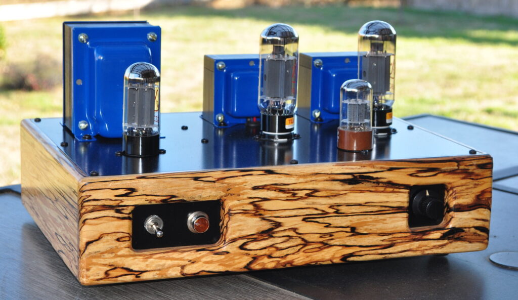
This amplifier was a direct outgrowth of the 6L6 Optimization Study. Having performed the study of the 6L6 tubes in an SE-UL configuration, and seeing the excellent performance which could be achieved, I decided to put the data into a practical application. This amplifier is the result.
Those with sharp eyes may notice that this amplifier shares a marked external similarity with 6V6 Marblewood Amplifier. This similarity flows mostly from the layout of the top plate and the similarities in the tone and pattern of the two wooden chassis. However there are some major differences which make this a far different design overall. Also, whereas I tend to prefer to run 6L6 tubes in the Marblewood amp these days, this amplifier makes much better use of the bigger 6L6GC tubes.
The Electrical Design
The first step in putting the 6L6 optimization data to use was to pick an operating point for the power stages. One surprise from the 6L6 study was the discovery that the overall distortion was very low regardless of the operating point chosen. This allowed the operating point to be chosen based on other criteria. Here is the set of optimized operating point data from that study.

At this point I had a thought. Since I had already produced a number of lower power amplifiers I decided to maximize the power output from the 6L6s. Not only this, I wanted to be able to swap in KT88/6550 power tubes with no other modifications. So I chose the bottommost line from this table with a B+ of 400Vdc, a plate voltage of ≈350v, a bias voltage of ≈32vdc, and a total cathode current of ≈68mA.
This design point would yield in the neighborhood of 7W per channel of nice clean sound out of the 6L6s. It also turns out to be a reasonable point to operate the KT88 tubes. My test data from a KT88 with a B+ of 400v and a 470Ω cathode bias resistor showed a plate voltage of ≈350v, a cathode bias voltage of ≈36v, and a total cathode current of ≈76mA. This is near the middle of the KT88 UL plate characteristics curves at this plate voltage.
In order to achieve a reasonable end to end power sensitivity for the amplifier, I chose to design using the higher gain (µ≈70) 6SL7 as a driver in a single ended common cathode topology. I also chose an operating point which would allow the insertion of a 6SN7 with no modifications. This option would be advantageous for those using a higher drive level or those wishing to use a preamp with the amplifier. Here is the 6SL7 load line design.
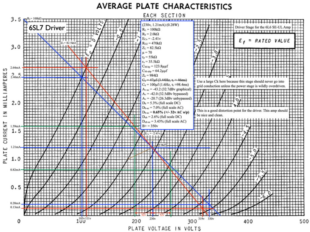
This 6SL7 operating point provides ample amplification and very good distortion characteristics for the driver stage. It also provides enough drive voltage to fully drive the big KT88s with a reasonable line level input.
After calculating the appropriate coupling characteristics, here is the final schematic (signal channel) I recorded for the amplifier.
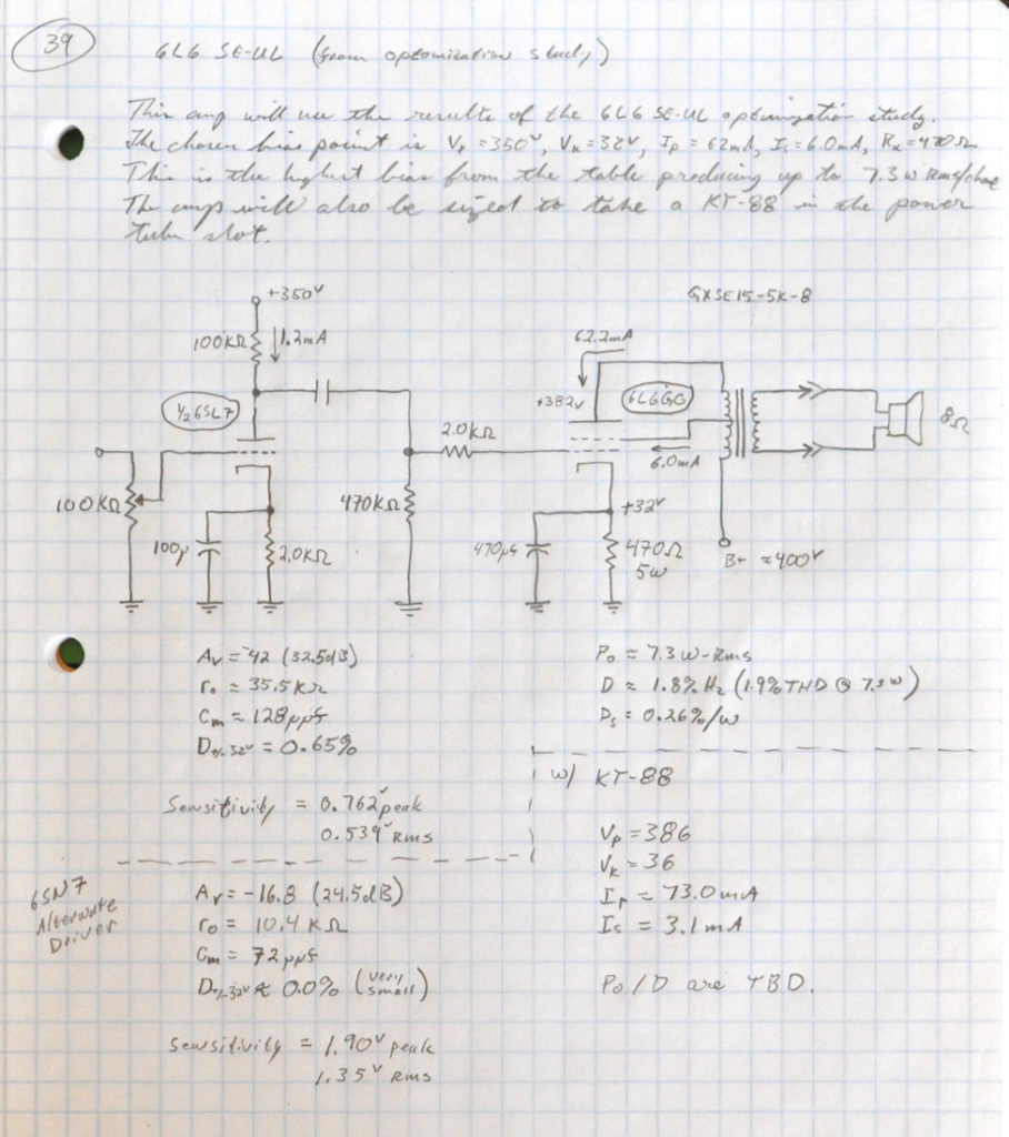
This is just a snapshot of a page out of my design notebook. The calculated design power sensitivities for both drivers are recorded in my notebook. The drive with the 6SN7 is a full 8dB lower allowing more voltage drive to reach full power. The calculated coupling capacitor (value not shown above) is 0.1µf.
In this schematic I also specified an Edcor GXSE15-5K output transformer. From the current levels involved I could have used the GXSE10 series but I wanted something else. One problem with UL amplifiers is the rather large effective plate resistance of the power tubes in this topology, which can limit low end performance. I chose the larger primary inductance of the 15W output transformers to help compensate for this. I also wanted the additional magnetic flux margin in the core of the GXSE15 to handle the higher flux from the KT88 bias point.
The power supply design for this amplifier was supposed to use a transformer I had on the shelf with an 800VAC secondary. I figured I could just use an appropriately large dropping resistor and all would be well. However, there was a hitch. The resultant no load DC voltage using this transformer was over 550VDC. This meant that I needed power supply capacitors rated at at least 600VDC for safety margin. These proved to be prohibitively expensive. So I decided to order a new XPWR178 transformer from Edcor with a high voltage secondary of 660VAC.
The no load secondary voltage of the new transformer was ≈700VAC. The Edcor power transformers are rated for specified voltage at full load. I knew this and had assumed it when ordering. This means that the no load dc voltage is in the neighborhood of 495VDC. As such, even though I have no intention of operating the amp without power tubes installed, I wanted capacitors (both filter and coupling) that could handle the voltage. For the filter capacitors I went with JJ ANH series electrolytic capacitors. For the coupling capacitors I went with Vishay 716 series capacitors with a 630VDC rating. Here is the resultant power supply schematic.
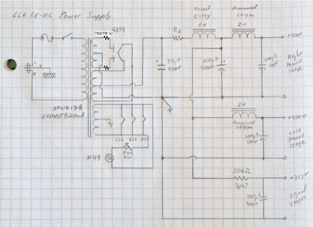
Note: I have added fixed 75Ω/5W resistors in series with the rectifier plate leads. This change is required to prevent the arc over of some GZ34/5AR4 rectifiers. This change is recommended for all builds of this amplifier design.
This design uses separate chokes on the power stages to provide excellent channel separation. The natural PSRR ratio of the driver stage in combination with a 30µf filter capacitor (the schematic above shows 100µf but I used a 30µf in the build) provides the channel separation in the driver. This amplifier also incorporates my now standard dimmable power indicator.
The Build
With the electrical design of the amplifier complete, it was time to think about the chassis. The wood I finally decided to use for this chassis was spalted alder. Here are the slabs as they came into my workshop.
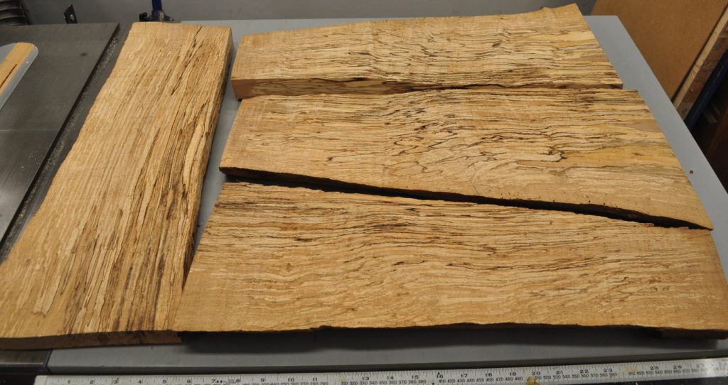
This particular wood has an interesting history.
This wood comes from a log cutoff that served as an anvil stand in my workshop for about 20 years. In 2015, when I was moving my shop across country, I removed the anvil and gave the wood log to a friend for his wood pile. I figured I could get a new log to use as an anvil stand anywhere I went.
He took the log and placed the cutoff next to his wood pile butt end down on the bare earth. And there it sat, in the rain and weather, for several years. Then a couple of years ago while cutting wood, he decided to cut the round. When he sliced the log lengthwise with his chainsaw he saw the spalting. So he slabbed the log and set the pieces inside his wood shed to dry. I was unaware of any of this.
Now, I had moved back to the same small town I left only a couple years later in 2017. So about a year ago, my friend came to visit and showed me the wood he’d brought. I decided that this was the ideal wood to use for this project.
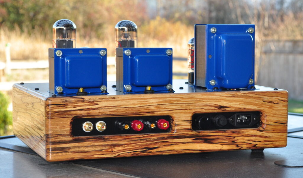
Here’s how those slabs of rough wood above look as a finished chassis with five coats of oil finish.
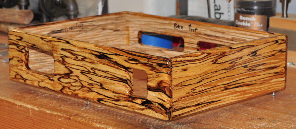
The layout for the internal of the amplifier was a little more complicated but I managed to fit everything in with a little room to spare. Here is the diagram of the internal layout.
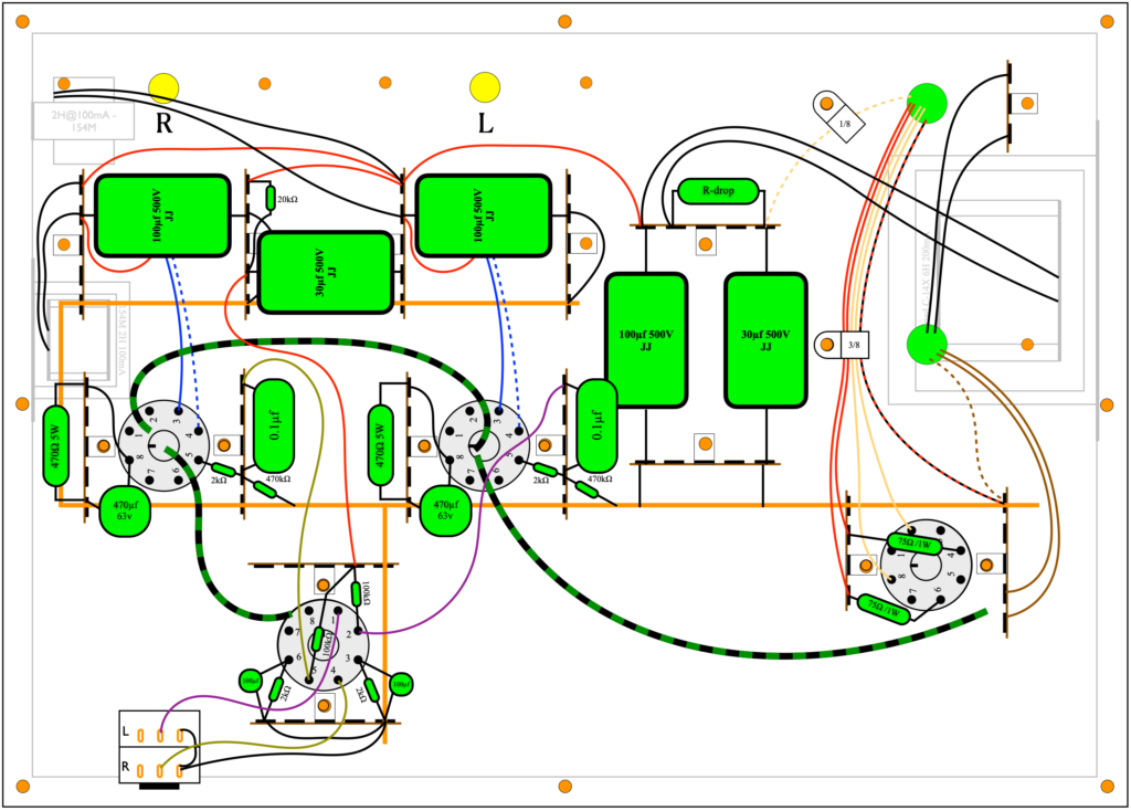
Note: Please note the addition of 75Ω/1W resistors in series with the rectifier plate leads.
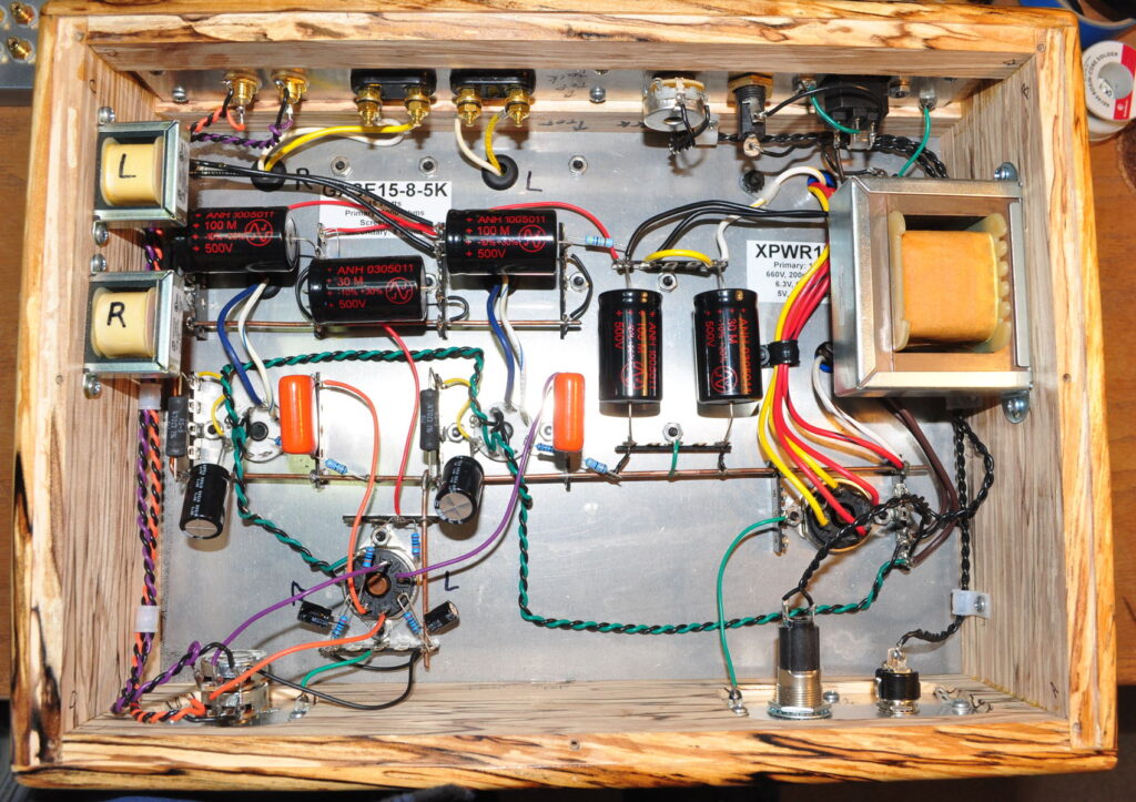
The main filter choke is on the right attached to the inside of the chassis. The two small 2H filter chokes for the power stages are on the left had side under the right channel output transformer, also attached to the chassis wall. Here’s what it looks like from the underside with all the wiring complete.
Testing
The first surprise of this build came when sizing the power supply dropping resistor. When I chose the XPWR178 power transformer, I had known that the B+ would be close to the target, but I had assumed it would be a little high. When I first applied power with no dropping resistor in place, the B+ at the power stage was ≈385VDC. This is about 3.8% below the 400v target voltage.
This lower B+ voltage doesn’t constitute a problem as it’s still very close to the target. However it does mean that no B+ dropping resistor is required. In the picture above, the bright yellow wire between the positive terminals of the two vertically oriented filter capacitors is where the dropping resistor would have been placed. Here are the resultant critical voltages at the the signal and power stages.

The drop in B+ only resulted in a less than 5v falloff in plate voltage on the power stages. The cathode voltage is slightly lower than target (≈2.5v or ≈8%) but not enough about which to worry.
The basic performance of the amplifier is very good and very close to the target. Here is the summary performance data for both channels.
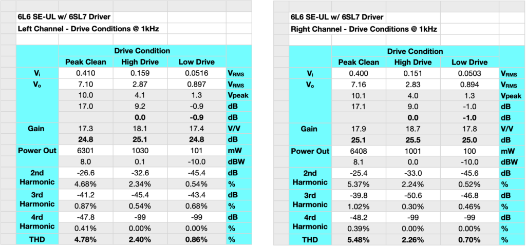
This data shows the performance for both channels at three different drive conditions. The first of these I call “Peak Clean”. This is determined from simply watching the output waveform on the oscilloscope and increasing the drive until I can just see some flattening of the output sine wave peaks. The other two drive conditions are the required drive for output powers of 1W and 100mW. This summary data is mid-band data taken at a frequency of ≈1kHz.
As can be seen from the data, the amp peaks out at around 8dBw or 6.3 watts per channel. It can obviously go higher than this, but this is where the harmonics really start to grow. Beyond this drive point the full set of harmonics (even and odd) start to grow and the sound of the amplifier begins to approximate that of a transistor amplifier. My target power was the 7.3W per channel of the optimization study. But with the falloff in B+ this is a reasonable result. The difference between 7.3W and 6.3W is only about 6/10th of a dB. Not enough about which to worry.
At 1 watt the amp is nice and clean with around 2.4% THD which is virtually all second harmonic. This gives the amp a nice full sound at moderate volumes. At 100mW the THD is well below 1% which is imperceptible under real world listening conditions. This makes the sound very clean and true at low volumes. These are excellent results and about what was expected in a full amplifier.
With the 6SL7 in place the amp is relatively sensitive requiring only about 400mv rms to achieve full power. This makes this amplifier easy to drive regardless of the source being used. The amplifier was tested for frequency response at about 1/2 a dB below the “Peak Clean” drive conditions listed above. Here are the full bandwidth relative gain and phase plots.
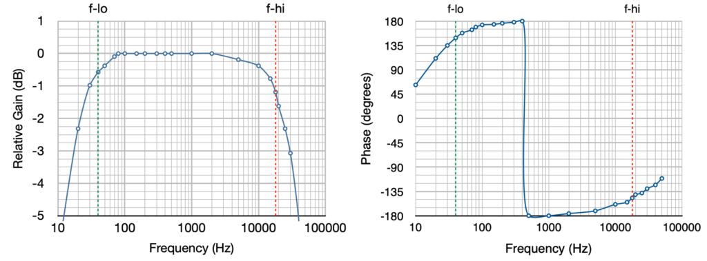
The 3dB bandwidth goes from ≈18Hz to ≈30kHz and the 1dB bandwidth goes from ≈30Hz to ≈17kHz. The low end rolloff at 20Hz is -2.3dB and the high end rolloff at 20kHz is -1.6dB. This is excellent performance for a SE-UL amplifier. Both the low frequency and high frequency roll offs are mild and well controlled.
The low end frequency performance shows the benefits of the larger 15W Edcor output transformers. This is due to the larger primary inductance of the 15W output transformers mentioned above. The other nice thing about these transformers is their low end distortion characteristics. These amplifiers are specified for a bandwidth of 40Hz to 18kHz. Below 40Hz there may not be enough cross sectional flux area in the core to support the waveform. This leads to low frequency distortion. But these transformers actually control this low frequency distortion rather well. Here is the distortions below 1kHz down to 20Hz.
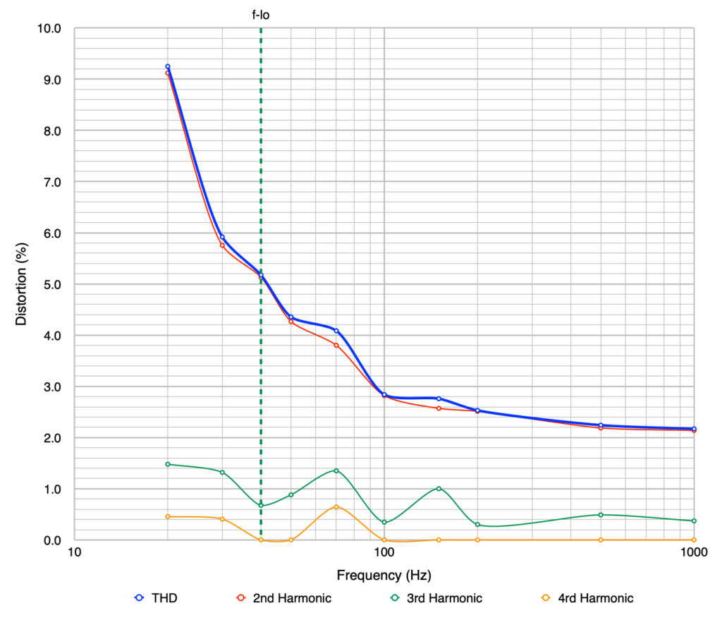
This is actually excellent performance for an amplifier of this type. There are two things of note in this instance. First is that the distortion is virtually all second harmonic. As such it is not discordant and is pleasant to the ear. The second is that it is virtually impossible for the human ear to hear this level of distortion below 100Hz. The result is an amplifier that has a clean and powerful low frequency performance.
Impressions
The most succinct description I can give is that the amplifier is clean, very fast, neutral in color, and musically powerful. It is an excellent example of the single ended UL topology. It is a solid performer with virtually any type of music but it really excels in the Classical and Vocal arenas. When listening to good classical scores I could easily pick out individual instruments and their details. When listening to vocals (even some Gregorian chant) the sound comes through crisp and true with no sign of blurring or excessive sibilance. Even the difficult overtones of choral voices came through clear and true.
The increased inductance of the output transformers did not have any noticeable effect on the speed and dexterity of the amplifier. The amp handled my test track for speed, Frederick The Great : Sonata in B-Flat - Allegro for recorder played by Michala Petri, without missing a single beat in the very fast, and very crisply played, score.
The amplifier reproduced bass heavy tracks with power and control and without any hint of booming or muddiness. Some sample tracks I used to test this included Not Fragile (quad mix) off the Bachman-Turner Overdrive “The Anthology” album and Cold Cold Heart off the Norah Jones “Come Away with Me” album. Both tracks have solid crisp bass lines intermixed with other instruments that really test an amplifier’s limits.
This design and build is an unqualified success. The amplifier sounds fabulous with crispness, precision, and power and without ever being fatiguing or straining on the ears. It is a pleasure to which to listen.
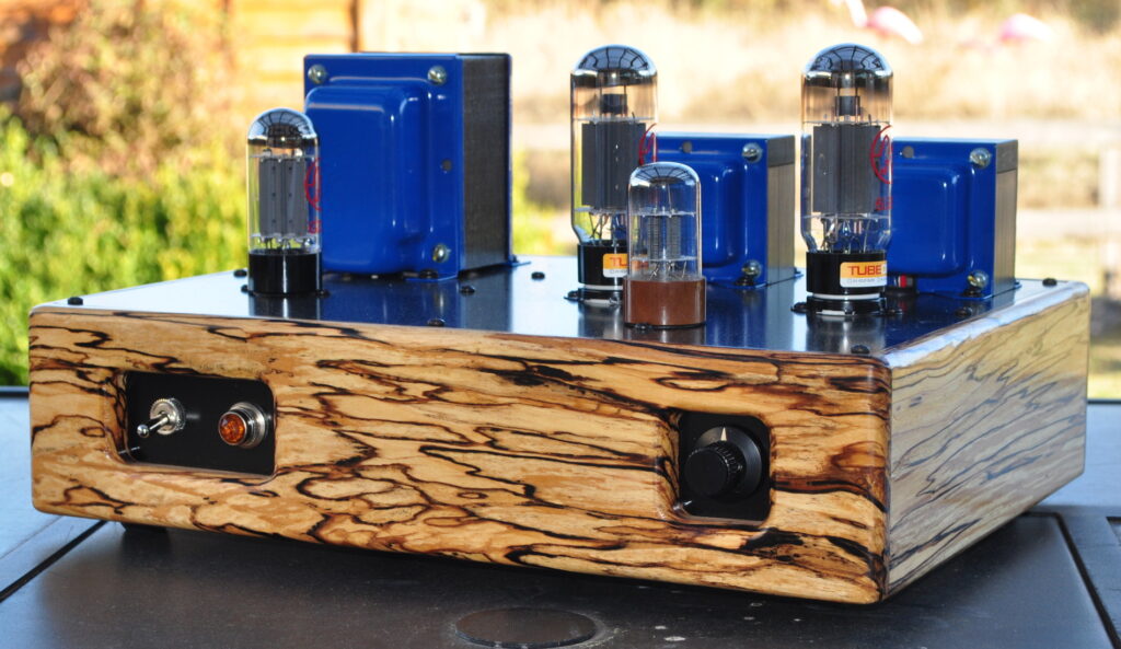
I would recommend this as a great “second amp” for anyone wishing to expand their skill and experience a bit. It also has enough power and precision to serve as a good main power amp in most systems in small to moderately sized rooms.
Configuration Options
There are two configuration modifications that can be made when using this amplifier. The first is that the driver may be substituted with a 6SN7 tube. This reduces the sensitivity of the amplifier by about 8dB allowing higher driving voltages or the use of a small preamplifier for tonal shaping.
The second modification is the substitution of power tubes. This amp will handle all the higher dissipation members of the 6L6 family including the 6L6GC and the 5881. It will also handle the KT88 and 6550 tubes without modification. These power tubes will be operated far below their limits but will provide good performance and long life.
So let me know what you think of the 6L6 “Spalted Alder” amplifier.