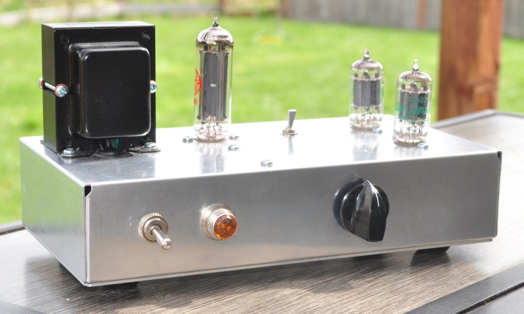
A Simple Preamp with a Specific Goal
The idea for this preamp has been floating around in my head for almost ten years. Ever since I built and posted about the “Universal” Preamp there has been a lot of discussion about a buffered preamp for adding tube color to lower input impedance solid state amplifiers. This discussion arose because the “Universal” Preamp, with its higher output impedance, is really not well suited for driving solid state amplifiers. So this winter I finally decided to tackle this project.
There is an obvious difference between this project and most of the others posted on my website. This project has no nice hardwood chassis and fine finish. Instead it’s built on a stock bare aluminum chassis box. The one I used is a BUD Industries AC-403. The reason for this difference is simple. This project started out as a quick diversion to fill my days while my workshop was too cold to do chassis work for a different amplifier. Too cold in the workshop meant I had to take a different approach. That and, I already had the chassis sitting on my parts shelf.
As it turned out, with components supplier issues, some design mistakes, chassis issues, and a slight rewire, this “quick project” took about four weeks to complete. But the results were excellent. This is a great project for adding just a touch of tube color to solid state amplifiers.
The Electrical Design
For the gain stage it would have been simple to just use the Universal Preamp design.
However, I wanted the ability to provide good gain control (i.e use a lower gain triode like the 12AU7) but provide more color and tonal shaping than the 12AU7 does in the Universal Preamp circuit design. So I went back to the 12AU7 and played with some different loads and bias points. I finally settled on a design which halves the plate load resistance and doubles the cathode bias resistance. To preserve the harmonic character of the preamp, the gain stage is followed by the buffer which is then followed by the volume control. This means there is no attenuation of the color provided by the gain stage at any volume setting.
Here is the final schematic. In this schematic all resistors are 1/2W except the 10kΩ cathode follower load resistor which should be 1W. The final value of Rd at which I arrived is 1kΩ/1W for a final B+ voltage of 297v.
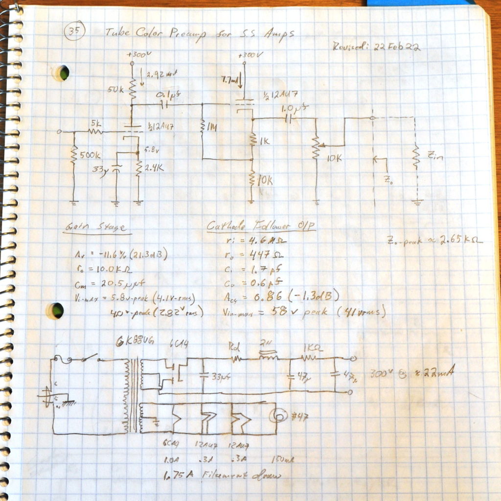
Note that the bias voltage on the gain stage should be 7.0v and not 5.8v. When I changed the B+ to 300v from 250v I recorded most of the changes in my notebook but missed that one.
This design uses an inexpensive Hammond 6K88VG power transformer, a 6CA4 rectifier, two 12AU7s, and just a handful of other components.
This design also has some nice features. Its output impedance is nice and low at all volume settings so it has no problems driving almost any amp with an input impedance above about 10kΩ. The end-to-end gain is just a little under 21dB. So a standard volume control set at 50% (12 o’clock) yields a unity end-to-end gain. As such, if you want to boost your source a little just dial the volume up from half way and if you want a little attenuation, just dial the volume down from half way. The full gain range of this preamp is just about -20dB to +20dB.
The Build
As I said above, this was supposed to be a quick project so the build had to be simple. I chose a BUD AC-403 chassis box from my parts shelf and started layout. This particular box is 9-1/2" (≈240mm) long by 5" (≈127mm) wide by 2" (≈50mm) deep. This provided ample space for all the components even though working inside the chassis was a little challenging. The layout is fairly clean with the power supply on the left (transformer, rectifier, power switch, indicator light, IEC connector, fuse holder) and the audio components on the right (12AU7s, volume control, ground lift, audio inputs and outputs). Here is the chassis box following drilling and clean up.
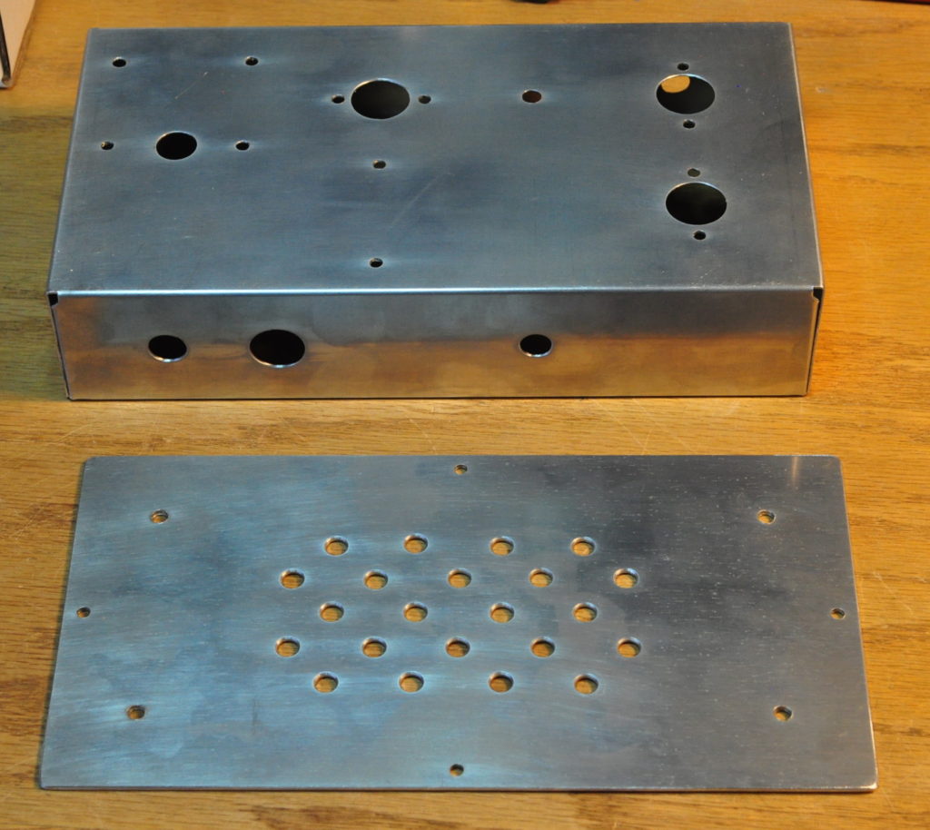
The bottom plate I just made from a sheet of 80 mil (≈2mm) 6061-T6 aluminum. It has ventilation holes and holes for mounting four rubber feet. The hole on the top of the chassis between the rectifier and one of the 12AU7s is for a ground lift switch. This is optional depending on how you wire up your systems.
The box provided enough room for layout but I don’t recommend using anything smaller for a chassis. Here is the inside of the chassis with everything mounted to the box (except the volume control) and the power supply wiring complete.
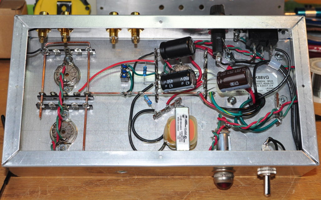
I really wouldn’t have wanted to work in a chassis any smaller than this.
In the above picture you can clearly see my telltale heavy signal ground bus and ubiquitous terminal strips for component mounting. The power supply wiring was fairly straight forward. However, as I moved to the signal side the lack of space began to really make things cramped. Here is the inside of the preamp with everything installed and wired in.
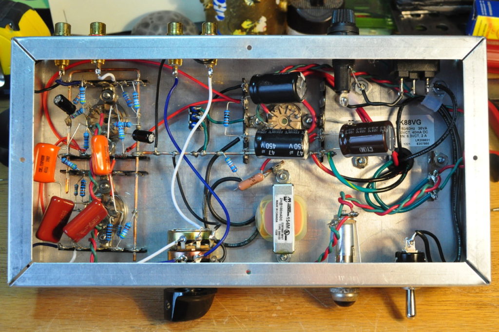
This is a nice layout and the preamp is dead quiet. But it was a challenge sometimes getting my fingers in there to get components installed. Here is a closeup of the gain section wiring in the final preamp.
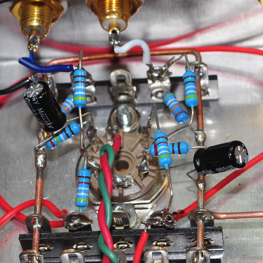
This image really doesn’t do justice to the three dimensional nature of the wiring and components. This is before the coupling capacitors were installed.
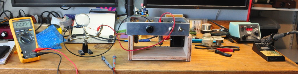
And here is the preamp as I select the final power supply dropping resistor to get the 300v B+ dialed in.
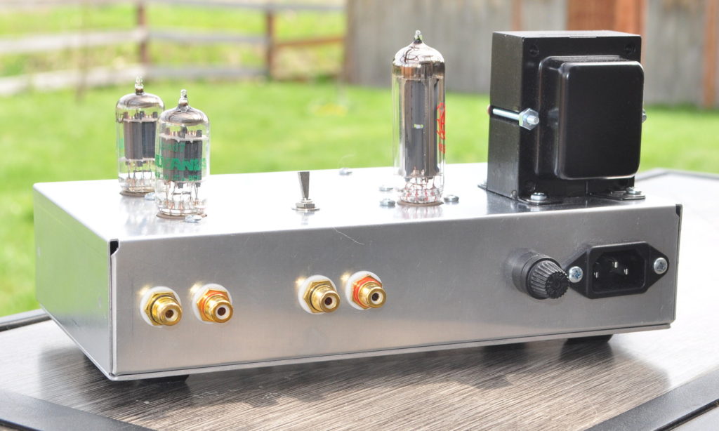
And for anyone curious, here is how the preamp looks from the back showing the signal and power connections.
Testing and Performance
Here are the initial spot checks on both channels. This is with the volume set a maximum.
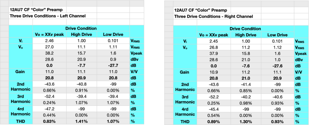
The gain in both channels is just about 21dB. The max input voltage before the harmonics start to rise is 2.45v-rms or ≈3.5v peak. This is 7.8dBv or 10dBu. At these levels the preamp should be good to go for just about any line level source.
As can be seen in the table, the preamp adds about 1% second harmonic color to the signal. This may not seem like much but it’s just about the right amount to add some nice warmth and depth to the typically sterile class-D amps with which I tested the preamp. Here is the passband gain and phase characteristics.
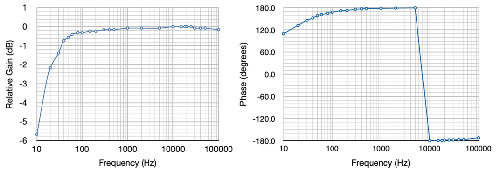
The amp is pretty flat at high frequency up until between 50kHz and 100kHz where Miller capacitance starts to take hold. A nice gentle rolloff at low frequencies is present. The response is down ≈0.7dB at 40Hz, ≈1.4dB at 30Hz, and ≈2.2dB at 20Hz. This is a good and properly controlled response curve. For anyone curious about the values, here is the table with direct measurements and calculations.
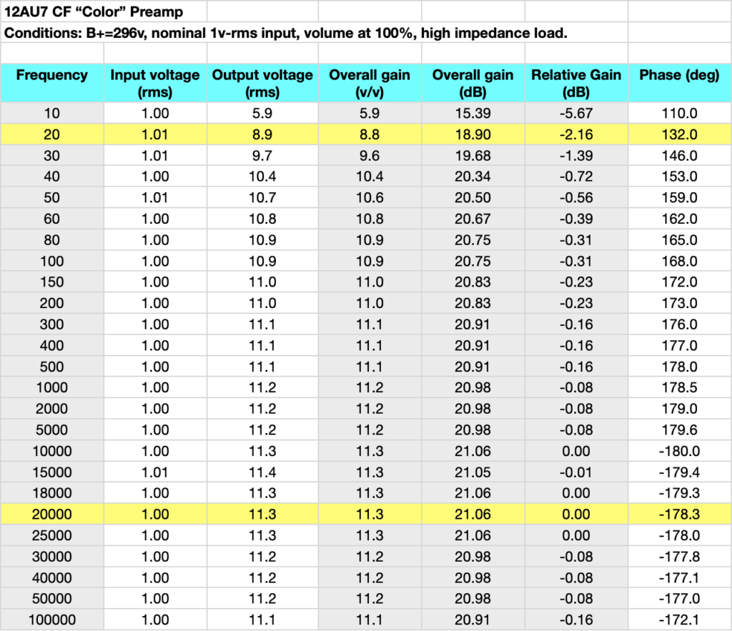
The minor variations in the pass band I directly attribute to the LSD values recorded in the table. As I’ve said many times “Real men don’t quibble over tenths of a dB”.
Summary
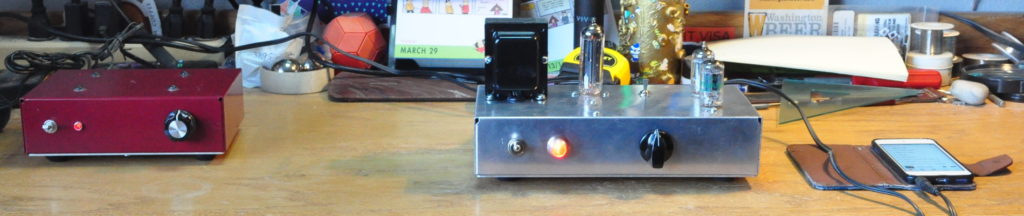
This started out a simple and quick project just to pass some time. However, the results achieved are really outstanding for something so simple. This preamp is a great way for someone to break into vacuum tube audio without having to abandon their solid state gear.