A Different Approach to “Universal”
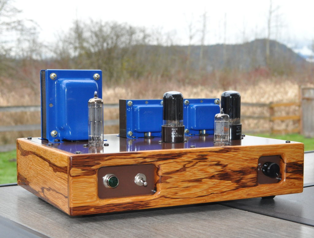
This amplifier started out with a stroll through a woodworking store in Oklahoma City, OK. What caught my eye was a single plank of a species of wood with which I’d never worked, “Marblewood” or zygia racemosum. The wood was expensive so I bought a single piece six inches wide and four feet long. Thus was the “Marblewood” amp born.
Now that I had the wood, I needed an amp to wrap it around. At his time I had just finished the rewire of the Lacewood amp using the information I had from the 6V6 bias optimization study. While doing that project, I thought that I should really design an entirely new 6V6 SE design specifically targeted at someone doing their first major tube amp build. This seemed like the proper opportunity to give it a try.
The Electrical Design
There were a few goals I had in mind as I started this design. Since it was targeted at a first time amp builder, I wanted to keep it as affordable as possible but still produce a really nice product. This meant a simple, but good quality, power supply, a minimalist topology to the amp circuit itself, and an elimination of anything that didn’t need to be there (within reason of course). I also wanted something else; I wanted the circuit to be versatile. I realized that a first time builder might like the ability to change things out, maybe try different tubes and explore the changes in sound that makes. So I ended up with the following schematic for the amplifier.
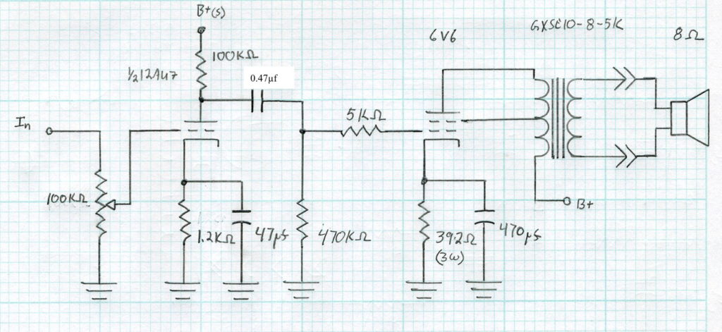
This deceptively simple design has a couple of things going for it. First it uses a 4S Universal preamp circuit as a driver, with the volume control moved to the front. This means that the 12AU7 driver tube can be substituted for a different sound and gain level with any of the following tubes: 12BH7, 12AV7, 12AY7, 12AT7, 12AZ7, and 12AX7. This is a total of seven common driver tubes which can be used with no modifications to the amp whatsoever.
Second, it uses the optimized bias point for the 6V6 power stage. This produces good results across a variety of B+ voltages with the 6V6 beam power tube. But as a serendipitous benefit, this bias resistor value also allows the use of several different power tubes as well. The design allows not only the 6V6 (for which it is specifically designed) but the 7408, 6L6, 5881, 6F6, and 6W6 as well. In combination with the driver tube variations, this is a total of 42 different driver/power tube combinations. That’s versatile!
In order to support all those power tubes, I needed an ample power supply with with enough filament winding power to supply the current hungry 1.2A 6W6 heaters. But I also wanted something else. I wanted to eliminate the extra heater circuit for the rectifier. So instead of one of the common 5V filament octal rectifiers, I settled on a 6CA4/EZ81 rectifier with a 6.3v heater and a unipotential cathode. This meant I only needed a single filament circuit for the entire amplifier. Here is the resultant power supply schematic.
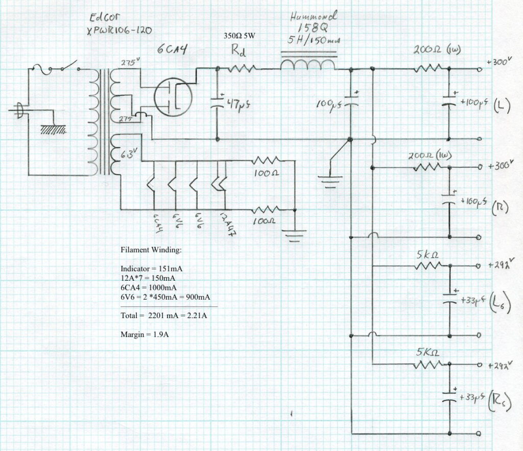
This power supply also has some nice features. As mentioned above, it only has a single filament winding which simplifies the power supply wiring. In addition, it uses only a single, relatively inexpensive, open frame filter choke. This helps contain the overall rice of the amplifier but, in combination with the additional R-C filter stages, still provides significant isolation guaranteeing a very deep and wide soundstage. Finally by using a power transformer with a substantial filament winding, there is enough margin to use the 6W6 power tubes with ease.
The Build
I wanted a layout for this design that a first time builder would not find too complicated. I also didn’t want it too large so that a standard commercial amp chassis could be used if desired. Here is the layout for the top upon which I settled.
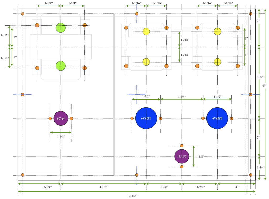
This layout puts the power supply on the left and the audio portion on the right. This also provides ample separation between the two sections. With simple modifications this layout can go on commercial chassis as small as 8”x12” without too much trouble. Here is a picture of the raw chassis and top plate sitting on the workbench in my wood shop.

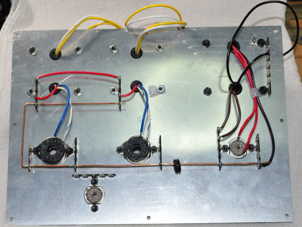
This picture illustrates an important concept I use during layout process. I use terminal strips with lugs on 3/8” centers. When I perform the initial layout I pay special attention to alignment and separation between items mounted to the top plate. This allows me to use existing mounting screws to mount the terminal strips. underneath without needing additional screws protruding on the top plate. This simple bit of planning really helps keep the top plates looking clean and uncluttered in the final builds.
At this point I perform as much wiring of the top plate outside of the chassis as possible. This ensures that I have very good access to every connection from pretty much any direction. This allows me to see everything and not have to contort my hands to get a soldering iron, solder, or pliers in position.
This approach also has another benefit. It allows me to perform some basic chassis wiring without having to work around the top plate. Since my chassis are essentially a wood “ring frame” that goes around the amp. Not having the top or bottom plate installed makes it a much simpler matter to run some of the other wiring. Here is a picture of the chassis after I’ve done some preliminary routing and wiring for the power transformer primary circuit and for the audio inputs and volume control.
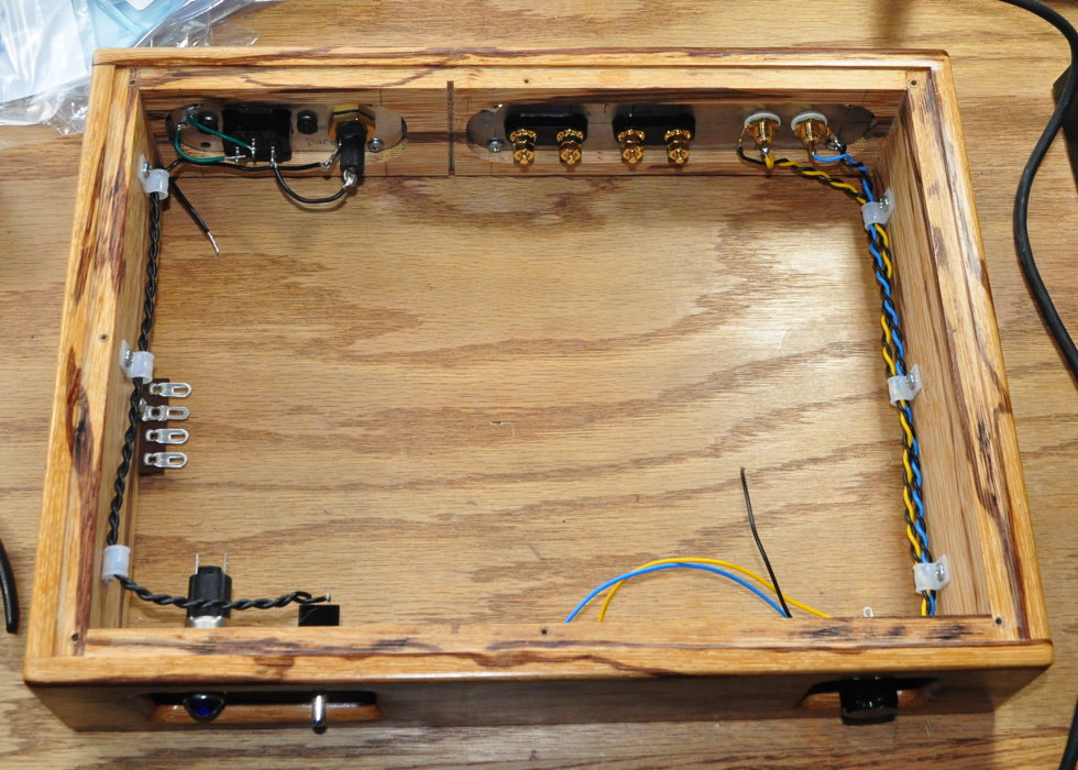
This wiring and routing was much easier to accomplish with access from both sides of the chassis. By performing the major wiring in two steps this way, it means that I have very few connections I have to make once the top plate is installed. Here is a picture of the inside of the chassis with the top plate installed and the wiring all completed except for the B+ dropping resistor.
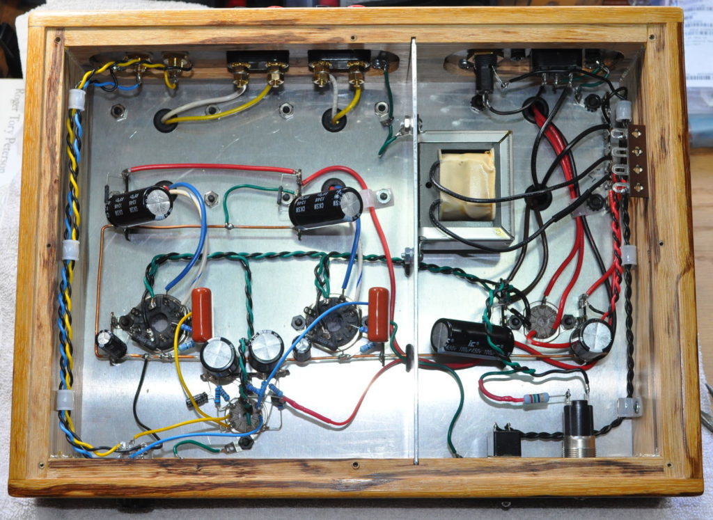
I will also note that I even installed the main power choke on the separator plate prior to sliding it into the slots cut in the chassis. I really think this is not too complicated a chassis layout. Even though it is point-to-point wired, it is not too crowded and it is relative easy to see all the connections.
Testing
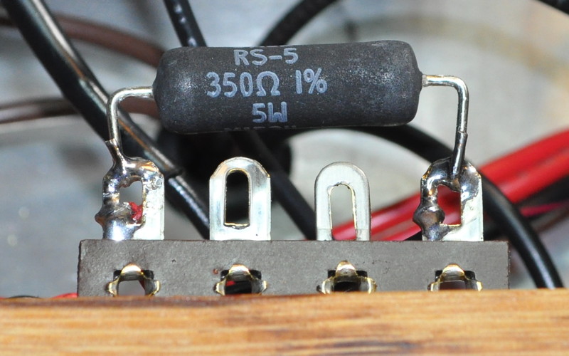
The initial testing was just to determine the appropriate B+ dropping resistor. After doing some spot checking I settled on a 350Ω resistor. Total current load for the amp with 6V6s is about 95mA. At 350Ω this equates to a power dissipation of about 3.16W. I settled on a nice 5W wire wound resistor shown below.
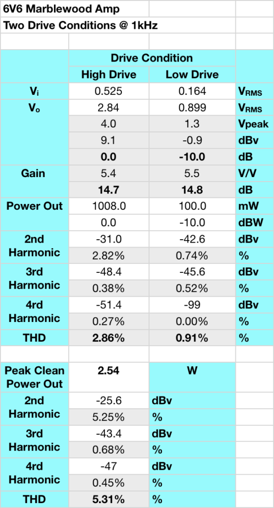
This is good behavior for an amplifier of this type. Distortion is very low at low output levels, at 1W the distortion is well controlled and virtually all 2nd harmonic, and even at 2.5W, it is still just at the ≈5% level and still virtually all 2nd harmonic. I am very satisfied with these results. As a point of interest, I define “Peak Clean Power Out” by visually watching the output waveform and increasing the levels until I just begin to see a little compression on the peaks of the sine wave. This is not the maximum output power of the amp but is a good reference for when the distortion characteristic changes from predominately 2nd harmonic to a more “transistor like” distortion characteristic. Here is the waveform plot for the 6V6s at “max clean power”.


So on paper the amp looks good. But what about how it sounds?
Impressions
The amp sounds fabulous. I initially spent about two hours trying all different types of music to see if I could find some sonic problems. I could not. It handled classical, opera, choral, jazz, rock, hip-hop, country, even Gregorian chant with no problems whatsoever. As is typical with these output transformers, the amp is very fast with excellent transient response.
In addition, the amp is dead silent with absolutely no int of hum or hiss. And when the music starts playing the sound stage is both deep and wide. Individual instruments and vocals seem to simply rise up out of the dark abyss.
This amp has truly excellent sound and performance. I would highly recommend this build for anyone looking to build a nice simple amp with great sound.
And About That Versatility?
So as I mentioned above, this circuit is designed specifically for the 6V6 power tube and 12AU7 driver. However, by using the “Universal” preamp design as the basis for the driver, and by using the ≈390Ω cathode bias resistor on the power stage, it allows this amp to handle a large number of different driver/power tube combinations. This is an especially nice attribute for someone just starting out with tube amps and wanting the ability to “try out” some different tubes without switches or having to make modifications.
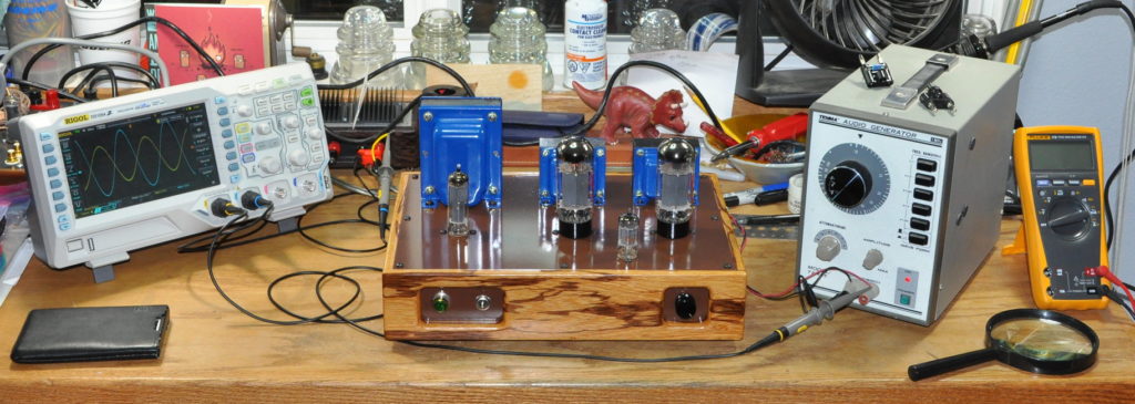
Just for reference, the acceptable driver tubes are: 12AU7, 12BH7, 12AV7, 12AY7, 12AT7, 12AZ7, and 12AX7. It should be noted that these tubes can produce wildly different gain values which will significantly change the sensitivity of the amplifier. When swapping driver tubes start with the volume setting very low and increase as necessary dependent on the drive level supplied to the amplifier. The acceptable power tubes are: 6V6, 7408, 6L6, 5881, 6F6, and 6W6. These all have slightly different levels of bias requiring different level of drive to reach full power. And each has a different sound quality when paired with any specific driver tube. This equates to 42 separate and distinct combinations of driver and power tubes you can use with this amp. Here is the amp under testing with a 12AU7 driver and a pair of JJ 6L6GC tubes.
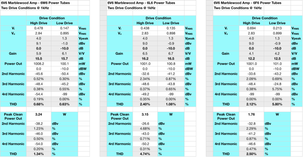
As can be seen from the data, it looks like the 6W6 is the best best for power and low distortion, the 6L6 is a good trade between the two, and the 6F6 is low power but also lower distortion than the 6V6 at moderate drive conditions.
Summary
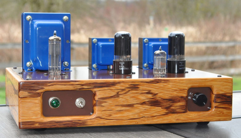
So let me know what you think of the “6V6 Marblewood Universal” amplifier.