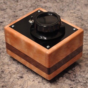
The Problem
Here’s the thing…
The Electrical Design
Now if I was going to build a control like this, I wanted a couple of inputs so that I could easily switch sources and compare things. I also didn’t want to induce any ground loops by adding this control. This drove me to the schematic you see here.
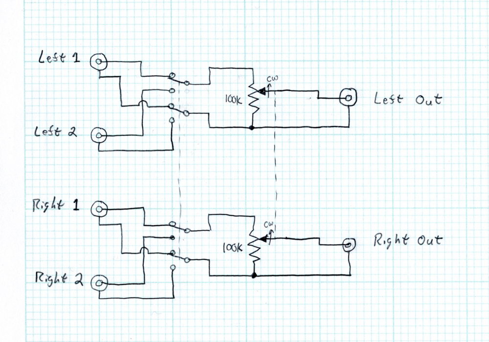
This unit is intended to be used with the tube equipment that I build and this is what drove me to the choice of the 100kΩ resistive elements. I didn’t want the control unduly loaded by the amplifier to which it is connected. Now depending on control position, the output impedance will start at 0Ω then increase to a peak value given in the following equation, and then fall (assuming the source impedance is less than 100kΩ) to the value of the source impedance shunted by a 100kΩ resistor.

Using the rule that the load should be at least four times the output impedance, this means that the amplifier to which the control is connected should have an input impedance of over 100kΩ. How much over is dependent on the output impedance of the source.
I also don’t want the control to overload the source to which it’s connected. This time, at the zero volume position, the input impedance will be the 100kΩ total resistance. And at full volume, the input impedance will be the 100kΩ resistance shunted by the input impedance of the following amplifier. So if we assume the amplifier has an impedance of at least 100kΩ as we just calculated, and assuming the rule that the load should be at least four times the output impedance, this means that our sources should have a maximum output impedance of approximately 12.5kΩ.
Usually these limitations are not an issue. If the sources are solid state virtually all devices will have an output impedance significantly lower than 12.5kΩ. Even with tube stages, for a bypassed common cathode stage the output impedance is the parallel combination of the plate resistance and the load resistance. For very high µ triodes (like the 12AX7 or the 6SL7) this might be a problem, but most line driver stages will have significantly lower output impedance than this limit.
The Build
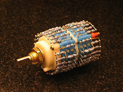
The other thing I didn’t want was a noisy control. So I decided to go with a stepped attenuator using metal film resistors. These are available all over the internet and I chose this one for $18 USD a piece.
I also need to remember to keep my grounds separated. So I chose gold plated RCA jacks that are insulated from the mounting surface. This meant that I could still use my favorite construction technique, wood with aluminum plates for the electrical components. I also selected a small form factor 4PDT switch to select inputs.
After choosing a nice piece of curly maple and some dark walnut for inlay and then cutting and painting some aluminum, I set forward on the construction. Here is a view of the insides before putting the bottom on the chassis.
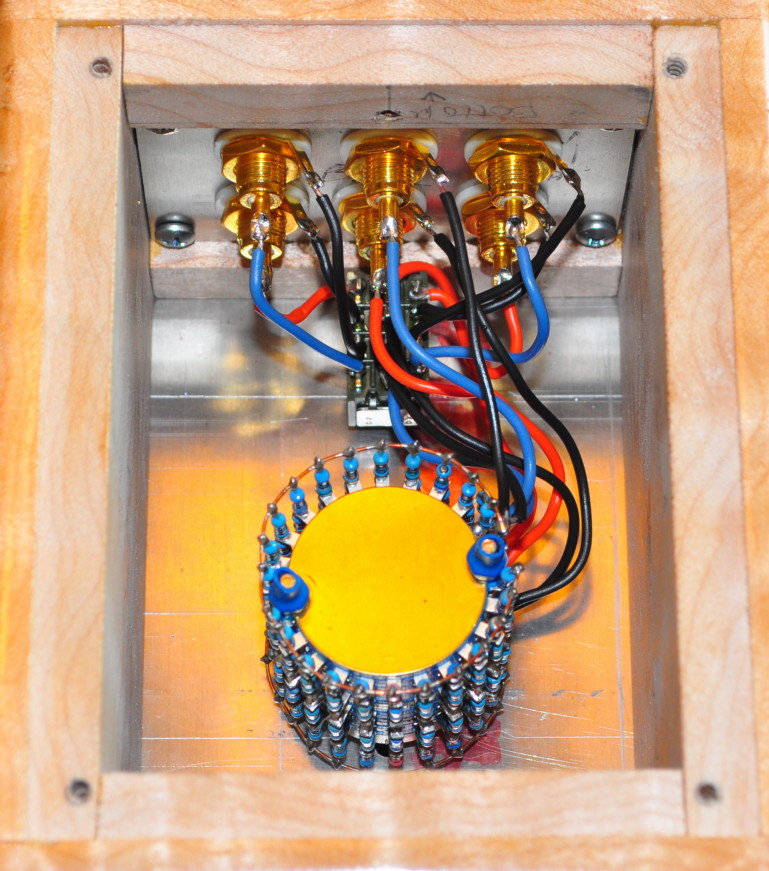
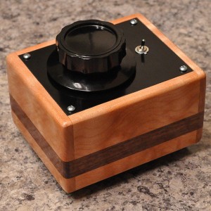
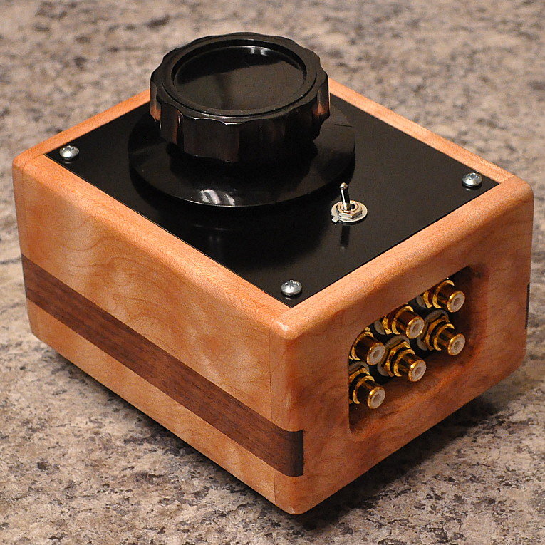
It was a little cramped but every thing went alright. Here is the finished unit showing the back where all the electrical connections are made.
The Results